
Motor rotor body

A technology of motor rotor and rotor shaft, applied in the direction of magnetic circuit rotating parts, magnetic circuit shape/style/structure, etc., can solve the problems of stress concentration, easy falling off of magnetic steel, weak anti-deformation ability, etc. The effect of reducing and improving mechanical strength and prolonging service life

Inactive Publication Date: 2012-04-11
浦江县合芯电子科技有限公司
View PDF12 Cites 8 Cited by
  • Summary
  • Abstract
  • Description
  • Claims
  • Application Information

AI Technical Summary

Problems solved by technology

But there are still the following deficiencies: 1. The rotor rotating at high speed, the above-mentioned scheme is easy to cause abnormal noise and noise 2. The stress is relatively concentrated and the deformation resistance is weak. The main fastening structure is the fixed ring 3. The mechanical strength is not high. Magnetic steel is easy to fall off and other technical problems

Method used


Image

  • Motor rotor body
  • Motor rotor body
  • Motor rotor body

Examples


Embodiment 1

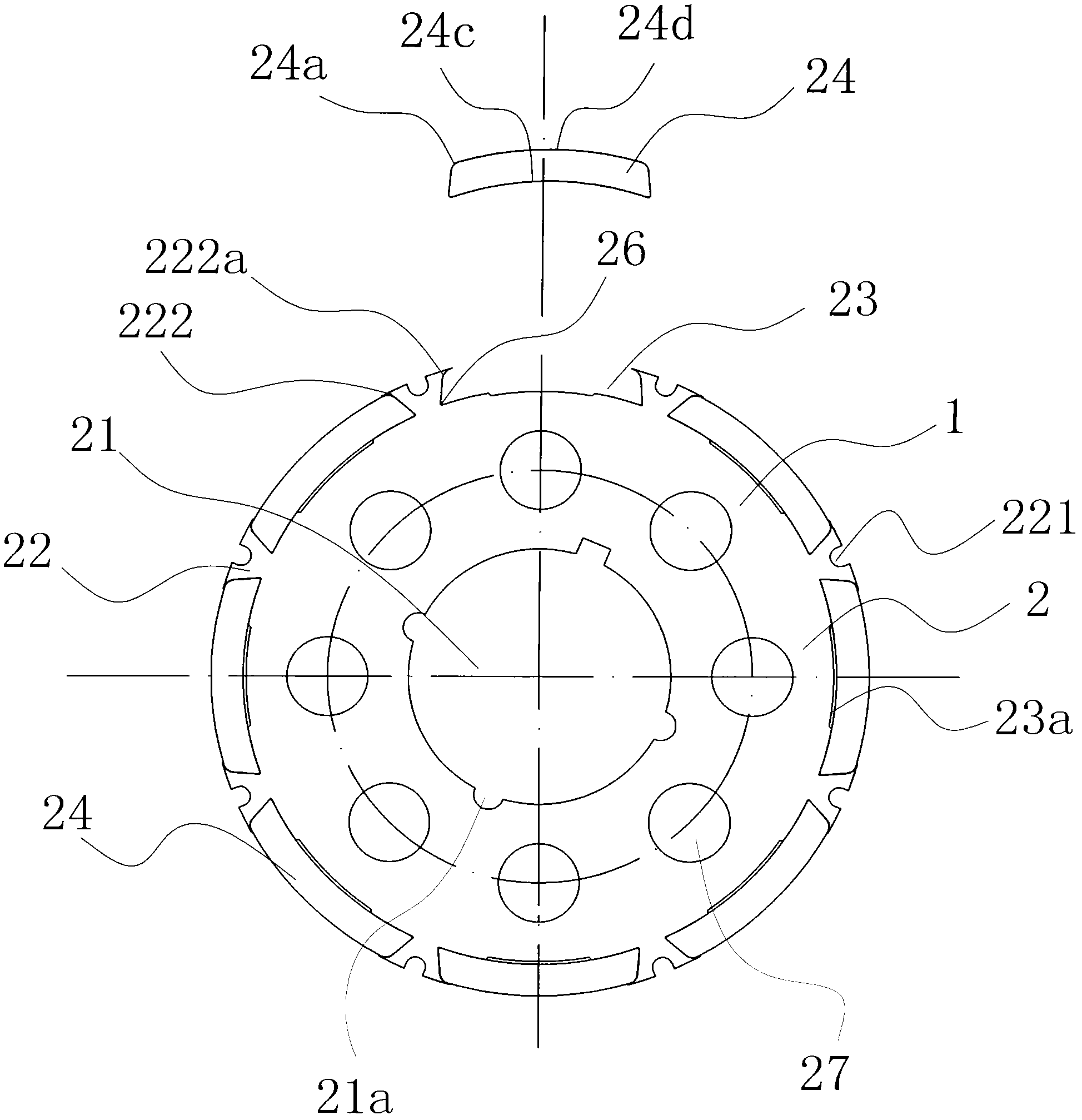
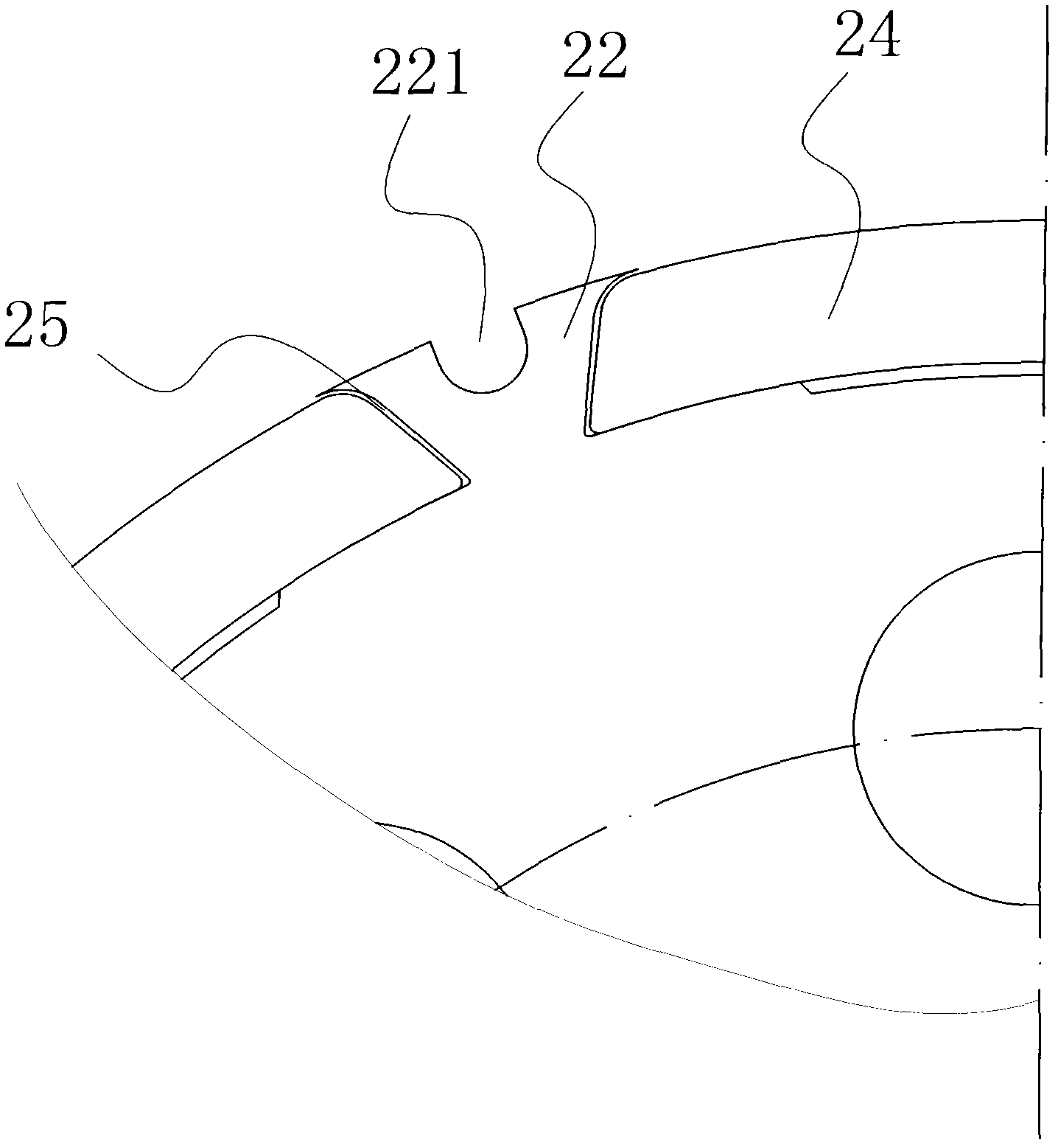
[0025] Such as figure 1 , 3 As shown, the rotor body of this motor includes a body 2 formed by stacking several rotor pieces 1. The center of the body 2 has a central hole 21 for fixing the rotor shaft. There are several outer ends and larger inner ends on the outer edge of the body 2. Small and evenly distributed dovetail bodies 22 in the circumferential direction, a dovetail groove 23 with a small outer end and a large inner end is formed between two adjacent dovetail bodies 22, a magnetic steel body 24 is housed in the dovetail groove 23, and a magnetic steel body 24 is housed in the dovetail body 22. There is a groove body 221 which can eliminate the gap 25 between the magnetic steel body 24 and the dovetail body 22 when it is expanded under the action of an external force, so that the magnetic steel body 24 is fixed in the dovetail groove 23 . On both sides of the outer end of the dovetail body 22 are respectively provided blocking feet 222 buckled on the outer feet of t...

Embodiment 2

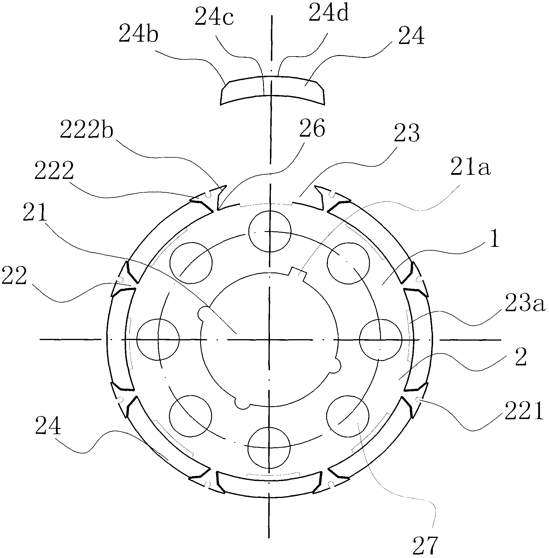
[0029] Such as figure 2 , 3 As shown, the inner surface of the blocking leg 222 has a first slope 222b, and the outer leg of the magnetic steel body 24 has a second slope 24b, and the above-mentioned first slope 222b coincides with the second slope 24b. In this embodiment, since the inner side of the blocking foot 222 has a first slope 222b, and the outer leg of the magnetic steel has a second slope 24b, the slope greatly increases the contact surface between the dovetail body 22 and the magnetic steel body 24, and the contact surface A large increase can better disperse the stress. When the groove body 221 is expanded under the action of an external force, the dovetail body 22 and the magnetic steel body 24 are closely fitted, that is, the first slope 222b coincides with the second slope 24b. At this time, The blocking feet 222 are also fastened to the outer feet of the magnetic steel body 24, so that the magnetic steel body 24 is firmly fixed in the dovetail groove 23, so ...


PUM


Abstract

The invention belongs to the technical field of a motor, and in particular relates to a motor rotor body. With the adoption of the motor rotor body, the technical problems that the traditional technical design is not rational and the like are solved. The motor rotor body comprises a body which is formed by overlapping a plurality of rotor sheets; the center of the body is provided with a central hole for fixing a rotor shaft and the outer edge of the body is provided with a plurality of dovetail bodies which are provided with big outer ends and small inner ends and are uniformly distributed in a circumferential direction; a dovetail groove which is provided with the small outer end and the big inner end is formed between two adjacent dovetail bodies and the dovetail groove is internally provided with a magnetic steel body; and the motor rotor body is characterized in that: the dovetail bodies are provided with slot bodies which can be used for eliminating the gap between the magnetic steel body and the dovetail bodies so as to fix the magnetic steel body into the dovetail groove when the slot bodies are expanded under the effects of external forces. The motor rotor body provided by the invention has the advantages of small abnormal sounds and noises, strong deformation resistance, high mechanical strength, long service life and the like.

Description

technical field [0001] The invention belongs to the technical field of motors, and in particular relates to a motor rotor body. Background technique [0002] The stator and the rotor are the two main parts of the motor. The rotor of the motor is formed by stacking several rotor punches. At present, the commonly used motors mostly use coil windings as the magnetic poles for the stators, and the rotors are equipped with magnetic steel as the magnetic poles on the outer edge. Magnets are usually bonded directly to the rotor. After this motor is used for a period of time, the magnetic steel bonded to the edge of the rotor will often fall off due to high temperature during the high-speed rotation of the rotor, which affects the normal operation of the motor and has a short service life. [0003] In order to improve this phenomenon, Chinese patent literature discloses a motor rotor [application number: 200920120283.8; authorized announcement number: CN 201466828 U], which include...

Claims


Application Information

Patent Timeline
IPC IPC(8): H02K1/27H02K1/28
Inventor 颜东红
Owner 浦江县合芯电子科技有限公司
Learn More