High-efficiency passive power factor correction circuit

A passive power factor, correction circuit technology, applied in the direction of high-efficiency power electronic conversion, output power conversion devices, electrical components, etc. Overcome the effects of low power factor, simple structure and small size

Inactive Publication Date: 2012-04-04
SOUTH CHINA UNIV OF TECH
View PDF3 Cites 4 Cited by
  • Summary
  • Abstract
  • Description
  • Claims
  • Application Information

AI Technical Summary

Problems solved by technology

Therefore, although the input AC voltage is a sine wave, the input AC current is pulse-like, and the waveform is severely distorted.
These pulse-shaped input currents contain a large number of harmonics. If a large number of current harmonic components flow back into the power grid, on the one hand, it will increase the level of harmonic noise in the power grid and cause harmonic "pollution" of the power grid. On the other hand, There will be a "secondary effect", that is, the current flows through the line impedance to form a harmonic voltage drop, which in turn distorts the grid voltage (original sine wave)
When these effects are serious, it will cause circuit failure and damage the substation equipment.

Method used


Image

  • High-efficiency passive power factor correction circuit
  • High-efficiency passive power factor correction circuit
  • High-efficiency passive power factor correction circuit

Examples


Embodiment Construction

[0023] The implementation of the present invention will be further described below in conjunction with the accompanying drawings, but the implementation of the present invention is not limited thereto.

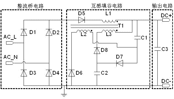
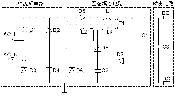
[0024] Such as figure 1 As shown, the composition and components of the high-efficiency passive power factor correction circuit of the present invention are as follows:

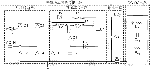
[0025] The power factor correction circuit suitable for passive high frequency includes three parts: rectifier bridge circuit, mutual inductance valley filling circuit and output circuit. The mutual inductance valley filling circuit is connected in parallel between the bridge rectifier circuit and the bridge arm of the output circuit.

[0026] The rectifier bridge circuit is composed of the first diode D1, the second diode D2, the third diode D3 and the fourth diode D4; the mutual inductance valley filling circuit is composed of the fifth diode D5, the Six diodes D6, the seventh diode D7, the eighth diode D...


PUM


Abstract

The invention relates to a high-efficiency passive power factor correction circuit, which comprises a rectifier bridge circuit, an output circuit and a mutual induction valley fill circuit; and the mutual induction valley fill circuit is connected in parallel between bridge arms of the rectifier circuit and the output circuit. The rectifier bridge circuit is composed of a first diode D1, a second diode D2, a third diode D3 and a fourth diode D4; the mutual induction valley fill circuit is composed of a fifth diode D5, a sixth diode D6, a seventh diode D7, an eighth diode D8, a first capacitor C1, a second capacitor C2 and a transformer T1; and the output circuit comprises a third capacitor C3.

Description

technical field [0001] The invention relates to power correction in an AC-DC conversion process, belongs to the field of switching power supplies, and in particular relates to a passive power factor correction circuit. Background technique [0002] Power factor (PF) is defined as the ratio of active power to apparent power, as shown in (1), where V in Indicates the input voltage, I indicates the effective value of the pulse current, I n Indicates the effective value of the nth harmonic, I 1 Indicates the effective value of the fundamental current, θ is the fundamental current I 1 with input voltage V in difference. [0003] (1) [0004] in, [0005] The total harmonic distortion factor (Total Harmonics Distortion, THD) is defined as the ratio of the total effective value of the high-order harmonic current component to the effective value of the fundamental current, as shown in (2). [0006] (2) [0007] The relationship ...

Claims


Application Information

Patent Timeline
Patent Type & Authority Applications(China)
IPC IPC(8): H02M1/42
CPCY02B70/123Y02B70/10
Inventor 杨祎巍李斌吴朝晖刘刚
Owner SOUTH CHINA UNIV OF TECH
Why Eureka
Try Eureka