
Dual-ring sealing device at gas compressor end of turbocharger

A technology of turbocharger and sealing device, applied in the direction of machine/engine, parts of pumping device for elastic fluid, mechanical equipment, etc., can solve the problem of oil leakage, poor oil return, and high oil level in crankcase problem, to prevent leakage and increase the reliability of the whole machine

Inactive Publication Date: 2012-04-04
KANGYUE TECH
View PDF6 Cites 9 Cited by
  • Summary
  • Abstract
  • Description
  • Claims
  • Application Information

AI Technical Summary

Problems solved by technology

[0004] 1. The pressure of the crankcase is too high, the oil return is not smooth at this time, and the oil leaks from the pressure of the supercharger and the sealing ring of the vortex end;
[0005] 2. The intake negative pressure is too high. At this time, the oil pressure of the middle shell is higher than the back pressure of the compressor wheel, and the oil leaks from the sealing ring of the pressure end;
[0006] 3. The structure of the oil return pipe is not suitable, such as too small hole diameter, large bend or not vertical, etc., which will cause poor oil return and oil leakage from the supercharger pressure and vortex end seal ring;
[0007] 4. The oil level in the crankcase is too high, and when it exceeds the oil return pipe, it will cause poor oil return, and the oil will leak from the turbocharger pressure and vortex end seal ring;
This sealing structure does not manage the space of the oil flow. When the engine operating conditions change, some lubricating oil will accumulate and overflow. Moreover, this sealing structure uses a sealing ring, one side is gas, and the other side is oil. Once the working conditions change and the pressure on both sides is unbalanced, leakage will occur
In addition, the socket connection between the thrust oil throwing plate 4 and the sealing ring seat 3 at the oil suction hole 9 increases the risk of mutual friction, and the reliability will be relatively poor

Method used


Image

  • Dual-ring sealing device at gas compressor end of turbocharger
  • Dual-ring sealing device at gas compressor end of turbocharger
  • Dual-ring sealing device at gas compressor end of turbocharger

Examples


Embodiment Construction

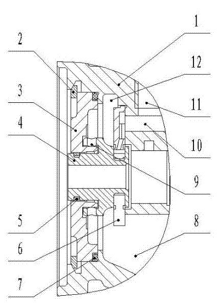
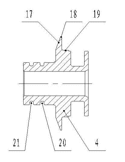
[0059] Examples such as figure 2 As shown, a double-ring sealing device at the compressor end of a turbocharger includes a middle shell 1, a thrust oil throwing pan 4 is arranged inside the middle shell 1, and a sealing ring is arranged between the thrust oil throwing pan 4 and the middle shell 1 The sleeve seat 3 and the seal ring sleeve seat 3 are set on the front end of the thrust oil throwing pan 4 and are sealed and rotationally connected with the thrust thrust oil throwing pan 4 .

[0060] There is a certain gap between the thrust oil throwing pan 4 and the sealing ring housing 3, and two sealing devices are arranged in the gap, and the gap between the two sealing devices forms a low-pressure chamber.

[0061] The middle shell 1 and the sealing ring seat 3 are sealed and connected with the elastic circlip 2 and the O-ring 7 through the hole.

[0062] Each sealing device includes a sealing ring 5 arranged between the thrust throwing oil pan 4 and the sealing ring seat 3...


PUM


Abstract

The invention discloses a dual-ring sealing device at a gas compressor end of a turbocharger. The dual-ring sealing device comprises a middle shell, wherein a thrust oil slinger is arranged in the middle shell; a sealing ring sleeve base is arranged between the thrust oil slinger and the middle shell; a gap is formed between the thrust oil slinger and the sealing ring sleeve base; two sealing devices are arranged in the gap; the gap between the two sealing devices forms a low-pressure cavity; two sealing rings are adopted; and a low-pressure cavity is formed between the two sealing rings and plays a role of buffering oil and gas on both sides. When the working condition varies, the pressure between the two sealing rings does not change immediately, and leakage is effectively prevented.

Description

technical field [0001] The invention relates to a turbocharger compressor end sealing device, in particular to a turbocharger compressor end double-ring sealing device, which belongs to the field of internal combustion engines. Background technique [0002] In recent years, turbocharging technology has developed rapidly. With the introduction of new technologies such as forward-inclined and backward-curved compressor impellers, mixed-flow turbines, three-dimensional flow field calculations, VGT superchargers, and two-stage supercharging, The performance of the turbocharger has been rapidly improved, but the structure of the turbocharger has not changed much, and the sealing problem is still a weak link, which is mainly manifested in the oil leakage when the supercharger is running. How to reduce the oil leakage has been solved. It has become a problem that all supercharger manufacturers focus on and urgently need to solve. The sealing structure of the supercharger is to pre...

Claims


Application Information

Patent Timeline
Patent Type & Authority Applications(China)
IPC IPC(8): F04D29/08
Inventor 王航桑悟海朱智富郭宗利郭晓伟宋丽华咸腾
Owner KANGYUE TECH
Learn More