Punching machine

A technology of machinery and indenters, applied in the field of stamping machinery, can solve the problems of complex structure, difficult adjustment, large number of parts, etc., and achieve the effect of preventing co-rotation and easy adjustment

Active Publication Date: 2012-04-04
MURATA MASCH LTD
View PDF8 Cites 11 Cited by
  • Summary
  • Abstract
  • Description
  • Claims
  • Application Information

AI Technical Summary

Problems solved by technology

[0004] Although there are cases where a mechanism that guides the indenter to advance in a straight line is provided in the conventional bending machine, the structure is complicated and the number of parts is large
In addition, although there are cases where a mechanism is provided to prevent co-rotation of the advancing and retreating parts of the ball screw mechanism, the reliability of preventing co-rotation with certainty is lacking.
In addition, in the case of adjusting the position of the indenter, it is necessary to adjust the mechanism for preventing the above-mentioned co-rotation, but this adjustment is difficult.

Method used


Image

  • Punching machine
  • Punching machine
  • Punching machine

Examples


Embodiment Construction

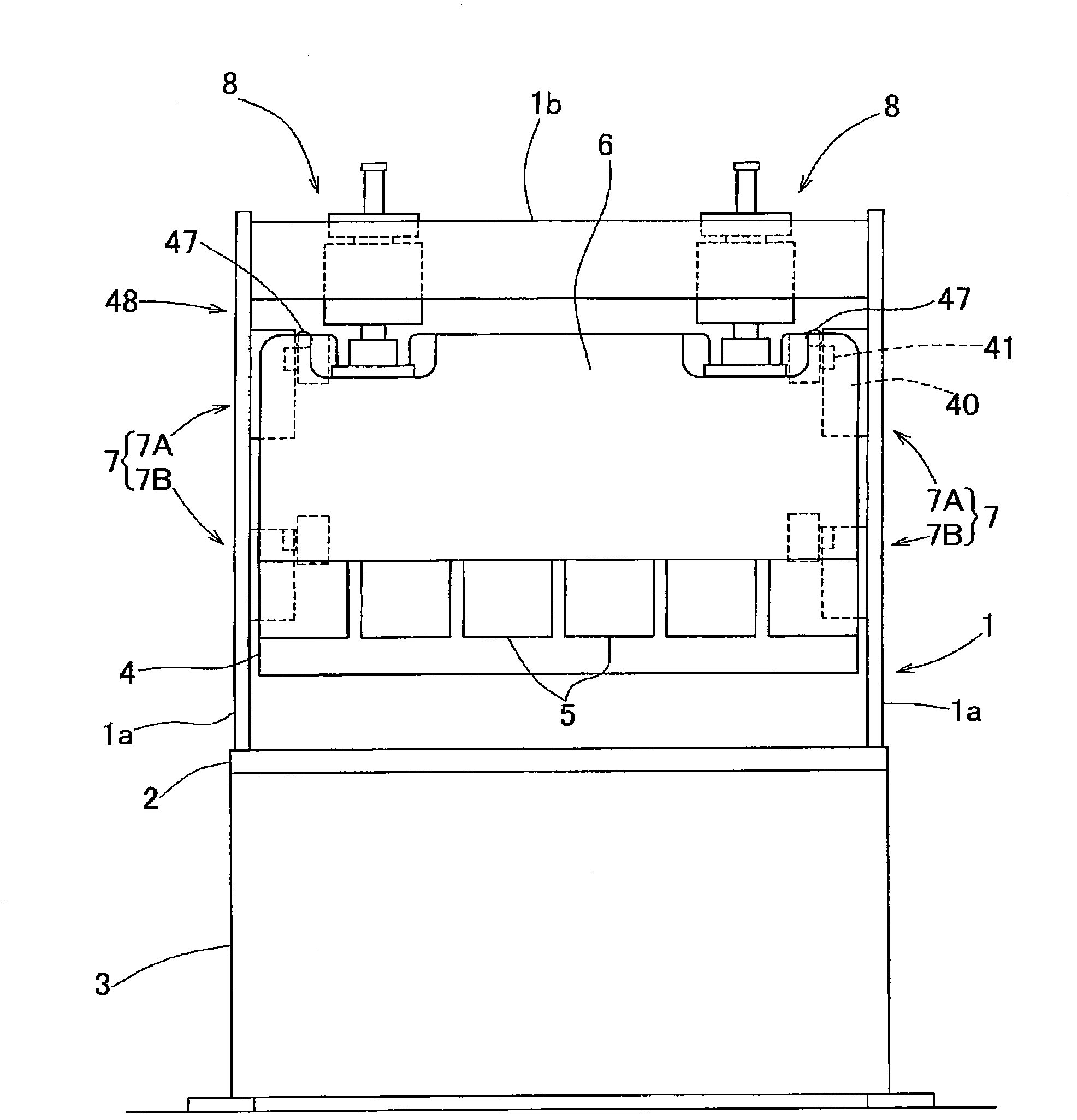
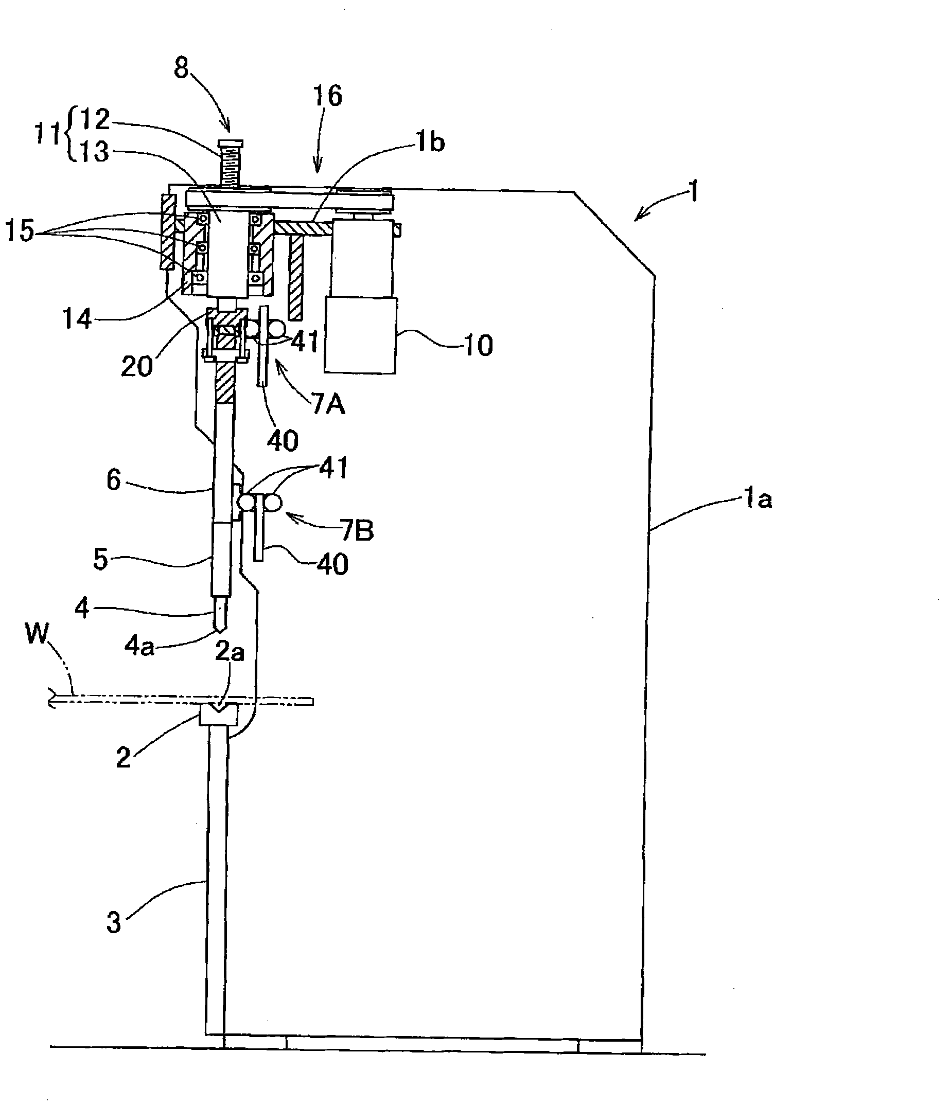
[0026] An embodiment of the present invention will be described with reference to the accompanying drawings. figure 1is a front view of the press machine according to this embodiment, figure 2 is its partially cut side view. This press machine is a plate bender. On the front side of the main body frame 1, a table 3 supporting a lower die 2 which is a fixed die and a ram 6 supporting an upper die 4 which is a movable die are provided. The workbench 3 is fixed relative to the main body frame 1 . Therefore, the lower mold 2 is set on the main body frame 1 via the table 3 . The indenter 6 is vertically supported by the main body frame 1 by the vertical guide mechanism 7 on the left and right sides, and is independently driven by the left and right sides by the left and right pair of vertical drive mechanisms 8 . The main body frame 1 includes: a pair of left and right side plates 1a; and a connecting frame portion 1b connecting the upper parts of the left and right side plates...


PUM


Abstract

The invention provides a punching machine with a simple structure, which can make a punch head linearly advance along the vertical direction even when the punch head is inclined and prevent an advancing and retreating part of a ball screw mechanism elevating the punch head from corotating relative to a rotary part. The punching machine comprises a punch head supported by an elevation guide mechanism on a main body frame in a way to be elevated on the two ends, and a pair of ball screw mechanisms equipped respectively on the left and the right and independently making the two end parts of the punch head elevated. The elevation guide mechanism allows the inclination of the two ends of the punch head. A rotation-preventing inclination-allowing connecting mechanism is equipped to make the advancing and retreating part of the ball screw mechanism, the threaded shaft, connected with the punch head on the premise that the threaded shaft core is prevented from rotating relatively and the inclination of the punch head is allowed. A linear advancement guide mechanism is equipped between the main body frame and the punch head for limiting the left-to-right movement of the punch head.

Description

technical field [0001] The present invention relates to a press machine such as a plate bender that independently raises and lowers left and right side portions of a ram by using a pair of left and right ball screw mechanisms. Background technique [0002] Generally, in a plate bending machine, the indenter supporting the upper mold at the lower end is supported to move up and down freely, and the left and right sides of the indenter are driven up and down by a pair of left and right lifting drive mechanisms. The plate material is bent in cooperation with the lower dies installed in a fixed position below the upper die (for example, Patent Document 1). Depending on the type of bending process, the load acting on the indenter is unbalanced left and right, and the indenter is often formed by inclining left and right to compensate for this load imbalance. However, since the lifting guide mechanism for guiding the lifting and lowering of the pressure head is provided based on t...

Claims


Application Information

Patent Timeline
Patent Type & Authority Applications(China)
IPC IPC(8): B21D5/02B30B15/04
Inventor 服部贤正渡边晃庸
Owner MURATA MASCH LTD
Why Eureka
Try Eureka