Swinging device with three-dimensional scanning laser radar

A technology of three-dimensional scanning and swinging device, applied in the direction of measurement device, electromagnetic wave re-radiation, utilization of re-radiation, etc., can solve the problems of not knowing the height information, unable to accurately identify obstacles, unable to obtain the height direction, etc., to change the limitations Effect

Active Publication Date: 2012-03-28
MILITARY TRANSPORTATION UNIV PLA
View PDF4 Cites 29 Cited by
  • Summary
  • Abstract
  • Description
  • Claims
  • Application Information

AI Technical Summary

Problems solved by technology

Using this information, the distance (depth) and width information of the obstacle can be obtained, but the height information is not known; in addition, if the obstacle is not in the scanning plane, the obstacle cannot be detected
Applying the radar to smart vehicles can only obtain the distance (depth) and width information of obstacles on the scanning plane, but cannot obtain any information in the height direction, and cannot accurately identify obstacles

Method used


Image

  • Swinging device with three-dimensional scanning laser radar
  • Swinging device with three-dimensional scanning laser radar
  • Swinging device with three-dimensional scanning laser radar

Examples


Embodiment Construction

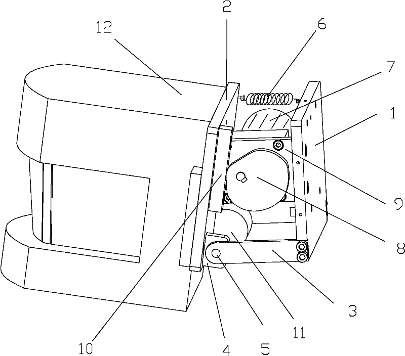
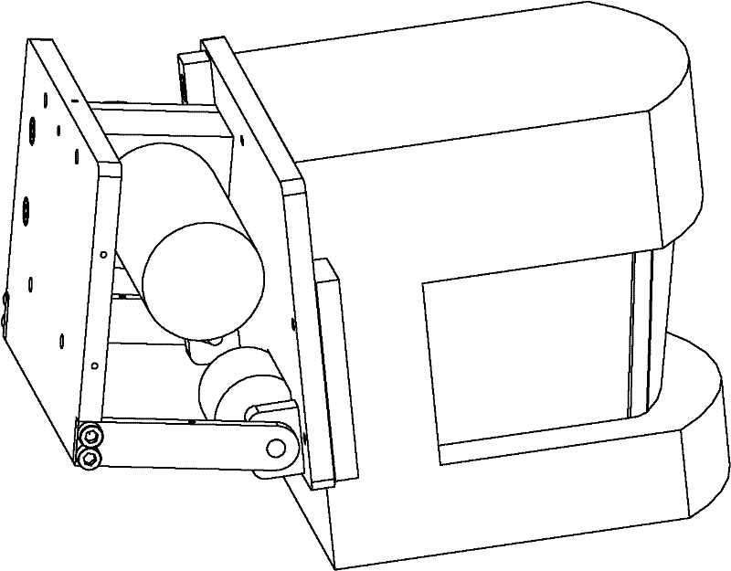
[0015] Below in conjunction with the preferred embodiments, the specific implementations provided according to the present invention are described in detail as follows: See the accompanying drawings for details, a laser radar is a three-dimensional scanning swing device, including a radar swing bracket and a vertical swing mechanism, the radar swing The bracket consists of an installation support surface 1, a swing plate 2, and the installation support surface and swing supports 3 on both sides of the swing plate to form an integral frame. The swing plate is provided with a connecting ear 4, and one end of the swing support is fixed to the side wall of the installation support surface Then, the other end of the swing bracket is connected to the swing plate through the connecting ear and the support shaft 5, the return spring 6 is hooked between the swing plate and the installation support surface, and the vertical direction swing mechanism is fixed on the inner side of the insta...


PUM


Abstract

The invention relates to a swinging device with a three-dimensional scanning laser radar. The swinging device is characterized by comprising a radar swinging bracket and a vertical direction swinging mechanism, wherein the entire frame of the radar swinging bracket consists of an installation support surface, a swinging plate, an installation support surface and swinging brackets on both sides ofthe swinging plate; the swinging plate is provided with a connecting lug; one end of each swinging frame is fixedly connected with the side wall of the installation support surface; the other end of each swinging bracket is in shaft connection with a support shaft and the swinging plate through the connecting lug; a reset spring is connected between the swinging plate and the installation supportsurface; and the inner side face of the installation support surface is fixedly connected with the vertical direction swinging mechanism. The swinging device has the advantages: the radar swinging bracket is arranged on an original radar installation surface, a radar is arranged on the swinging surface of the radar swinging bracket, and a cam is driven to swing along the vertical direction, so that nodding type vertical swinging of a SICK radar is realized, and a two-dimensional laser radar is converted into a three-dimensional scanning laser radar.

Description

technical field [0001] The invention belongs to a laser radar rangefinder, in particular to a swing device for three-dimensional scanning of the laser radar. Background technique [0002] The lidar emits pulsed laser light in all directions in the plane by rotating the mirror and the reflected light is received by the LMS. The time difference between reflection and reception is calculated by a timer to measure the distance from the obstacle to the radar. Such as image 3 As shown, the LMS291 laser radar of SICK company in Germany can realize two-dimensional 180° plane scanning and detect obstacles up to 80m away. This type of radar is used in smart vehicles to detect obstacles or other vehicles in front of the vehicle, so that smart vehicles can avoid obstacles or other vehicles and maintain a safe driving distance. SICK-LMS291 radar emits a laser beam at a certain frequency within 180° of the plane, reflects the beam when encountering an obstacle, and receives it by the LM...

Claims


Application Information

Patent Timeline
Patent Type & Authority Applications(China)
IPC IPC(8): G01S7/48G01S17/08
CPCG01S7/4817
Inventor 徐友春袁一赵明冯明月章永进贾鹏
Owner MILITARY TRANSPORTATION UNIV PLA
Why Eureka
Try Eureka