Eureka AIR delivers breakthrough ideas for toughest innovation challenges, trusted by R&D personnel around the world.

Garbage salvage ship

A technology for salvaging ships and garbage, which is applied in the cleaning of special-purpose ships, open water surfaces, ships, etc. It can solve the problems of clogged sludge pumps, thickened sludge, and low cleaning efficiency, and achieves low investment, small ship size, and easy production Effect

Inactive Publication Date: 2012-03-28
浙江省疏浚工程有限公司
View PDF7 Cites 4 Cited by
  • Summary
  • Abstract
  • Description
  • Claims
  • Application Information

AI Technical Summary

Problems solved by technology

[0002]At present, the pollution of rivers in our country is becoming more and more serious. There is a large amount of domestic waste, industrial waste and construction waste, which further aggravates the pollution of the river
At this stage, many river cleaning ships can only clean up the pollutants on the river surface, but cannot clean up the garbage in the silt, and the cleaning effect is not ideal.
If it is necessary to clean up the silt, most of the silt in the river channel is pumped out by dredgers for landfill. In this way, the cleaning efficiency is low
[0003] Chinese patent CN201559798U discloses a sludge garbage separation ship, which is characterized in that a sludge pump is provided in the power cabin, and the sludge pump simultaneously lifts the sludge and garbage to the garbage separation cabin for separation treatment. The problem is that the relatively large debris in the sludge cannot be lifted up by the sludge pump, especially when there are plastic belts or discarded fishing nets, which will block the sludge pump inlet
Chinese patent CN201864013U discloses a garbage salvage ship collection device, which contains a conveyor belt, but the conveyor belt is inconvenient to operate and has low efficiency

Method used


Image

  • Garbage salvage ship
  • Garbage salvage ship
  • Garbage salvage ship

Examples


Embodiment Construction

[0026] The present invention will be further described in detail below in conjunction with the drawings.

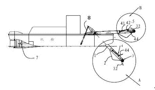
[0027] Such as figure 1 As shown, the garbage salvage ship includes a propeller 7 located at the stern of the ship, a diesel-driven oil pump located in the engine room of the hull, and a garbage collection mechanism located at the bow of the ship. The garbage collection mechanism includes a garbage hopper frame 1 and garbage under the garbage hopper frame 1. Bucket 2, a knife fishing mechanism 3 located at the front end of the garbage hopper frame 1, and a scraper mechanism 4 located on the garbage hopper frame 1. The knife fishing mechanism 3 includes a small sprocket 31, a first cylinder 33, a linkage mechanism 5 and a small sprocket hinged The arc-shaped fishing knife 32 on 31, the scraper mechanism 4 includes a second oil cylinder 41, a large sprocket 42, a link mechanism 5, and a scraper 44 which are hinged to each other in sequence, and a third oil cylinder 8 is hinged ...


PUM


Abstract

The invention relates to a dredging device and in particular relates to a garbage salvage ship for taking out garbage at a river bottom. The garbage salvage ship comprises a propeller at a stern, a diesel engine driving oil pump in a hull cabin and a garbage collecting mechanism at the fore body of the ship, wherein the garbage collecting mechanism comprises a garbage bucket frame, a garbage bucket positioned below the garbage bucket frame, a salvaging cutter mechanism in the front end of the garbage bucket frame and a scraper mechanism on the garbage bucket frame; the salvaging cutter mechanism comprises a small chain wheel, a first oil cylinder, a connecting rod mechanism and a salvaging cutter hinged on the small chain wheel; the scraper mechanism comprises a second oil cylinder, a big chain wheel, a connecting rod mechanism and a scraper which are mutually hinged; and the tail part of the garbage bucket frame is hinged with a third oil cylinder. Through the connecting rod mechanism, a chain transmission mechanism and a hydraulic transmission mechanism, the garbage salvage ship can be used for well performing the actions such as salvaging, extracting, tipping and scraping and the like on the garbage at the river bottom so as to realize the river bottom garbage salvage with diversity and complexity.

Description

Technical field [0001] The invention relates to a dredging device, in particular to a garbage salvage boat for clearing garbage at the bottom of the river. Background technique [0002] At present, river pollution in our country is becoming more and more serious. The main reason is that the silt in the river is thickened, and a large amount of garbage that cannot float on the water is dumped into the river, resulting in a large amount of domestic garbage, industrial waste and construction waste in the river silt, which is further aggravated The degree of pollution of the river. At this stage, many river cleaning vessels can only clean up pollutants on the surface of the river and cannot clean up the garbage in the silt, so the cleaning effect is very unsatisfactory. If silt cleaning is required, most of the silt in the river is pumped out by a dredger for landfill. In this way, the cleaning efficiency is low. [0003] Chinese patent CN201559798U discloses a sludge and garbage se...

Claims


Application Information

Patent Timeline
Patent Type & Authority Applications(China)
IPC IPC(8): B63B35/32E02B15/10
CPCY02A20/204
Inventor 劳浩兴罗显文武艺戚卫斌
Owner 浙江省疏浚工程有限公司
Why Eureka
Eureka Blog
Learn More