Injection head of die casting machine and lubrication structure thereof

A technology of lubricating structure and injection head, applied in the field of auxiliary structure of injection head, can solve problems such as damage of injection head, increase cost of foundry enterprises, stop production, etc., and achieve the advantages of reducing production cost, prolonging service life and improving service life. Effect

Active Publication Date: 2014-08-13
XIANGYANG MEILIXIN SCI & TECH
View PDF6 Cites 0 Cited by
  • Summary
  • Abstract
  • Description
  • Claims
  • Application Information

AI Technical Summary

Problems solved by technology

However, the working time of the injection head is a little longer, especially after a period of use. After the high temperature of the molten metal is transmitted to the injection head through the working end of the injection head, the working surface of the injection head is worn out during the long-term reciprocating movement. There will be a phenomenon that the injection head is stuck, and the injection head cannot be pulled out from the pressure chamber and is bonded to the molten metal, which may cause shutdown and production stoppage, or cause damage to the injection head and the pressure chamber and require Replacing the injection head and the pressure chamber results in a shorter working life of the injection head. Generally, the life of the injection head is only 700 to 1,000 times, which cannot meet the needs of the foundry enterprise for the die-casting machine, and also increases the cost of the foundry enterprise.

Method used


Image

  • Injection head of die casting machine and lubrication structure thereof
  • Injection head of die casting machine and lubrication structure thereof
  • Injection head of die casting machine and lubrication structure thereof

Examples


Embodiment Construction

[0018] The present invention will be further described below in conjunction with the accompanying drawings and specific embodiments.

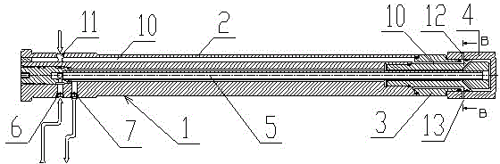
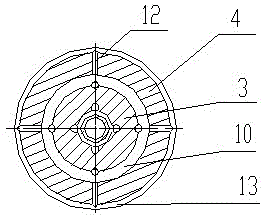
[0019] Such as figure 1 , 2 As shown, the injection head of the die-casting machine of the present invention includes an injection head body 1, and the injection head body 1 is composed of an injection rod 2, a connecting head 3 and an injection end 4 connected in sequence. A cooling water channel 5 is provided inside the head body 1, and a cooling water inlet 6 and a cooling water outlet 7 are provided on the injection rod 2. The cooling water inlet 6 and the cooling water outlet 7 communicate with the cooling water channel 5, and the external cooling water passes through the cooling water The inlet 6 enters the cooling water channel 5 in the nozzle body 1 , and then flows out through the cooling water outlet 7 to cool the nozzle body 1 . The injection end 4 is used as the working end of the injection head, and is in contact with the high-te...


PUM


Abstract

The invention provides an injection head of a die casting machine, which comprises an injection head body, wherein the injection head body comprises an injection rod, a connection head and an injection terminal which are sequentially connected; lubrication oil passages are correspondingly arranged in the injection rod, the connection head and the injection terminal; the lubrication oil passages on the injection rod, the connection head and the injection terminal are communicated with each other to form a lubrication oil channel; a lubrication oil inlet is arranged on the injection rod; a plurality of radial lubrication oil outlets are arranged on the injection terminal; and the lubrication oil inlet and the lubrication oil outlets are communicated with the lubrication oil passages. The injection head provided by the invention changes the defect that the working surface of the injection head can not be lubricated; by adding oil pump and oil hole structures, the lubrication structure of the injection head pressurizes lubrication oil onto the working surface, thereby ensuring that the working surface is in a lubrication state all the time; the service life of the injection head and the injection chamber can be effectively prolonged by about 5 times; and the seizure caused by the heat expansion of the injection head can be effectively avoided.

Description

technical field [0001] The invention relates to an auxiliary structure of an injection head of a die-casting machine in the foundry industry, in particular to an injection head of a die-casting machine and a lubricating structure thereof. Background technique [0002] Die-casting machine is a common equipment in the field of forming technology in the machinery industry. It is an industrial machine that hydraulically injects molten metal into a die-casting mold for cooling and forming under pressure, and obtains solid metal castings after the mold is opened. [0003] The injection head is an important component on the die-casting machine. It usually moves back and forth horizontally or vertically to press the liquid metal into the die-casting mold. The injection head is generally connected to the die-casting mold through the die-casting machine and the pressure chamber; the injection head One end (working end) is in contact with the high-temperature metal liquid, and the temp...

Claims


Application Information

Patent Timeline
Patent Type & Authority Patents(China)
IPC IPC(8): B22D17/30
Inventor 熊孝国
Owner XIANGYANG MEILIXIN SCI & TECH
Why Eureka
Try Eureka