Insert, holder, and cutting tool using said insert and holder

A technology of inserts and tool holders, which is applied in the field of cutting tools, can solve the problems of increased repeat installation accuracy, reduced rigidity, and reduced cross-sectional area of ​​inserts, etc., and achieves good repeatability, sufficient rigidity, and vibration suppression.

Active Publication Date: 2012-03-21
KYOCERA CORP
View PDF5 Cites 4 Cited by
  • Summary
  • Abstract
  • Description
  • Claims
  • Application Information

AI Technical Summary

Problems solved by technology

As a result, the variation in repeated mounting accuracy increases
In addition, since the upper surface side flat part is provided, there is a problem that the cross-sectional area of ​​the insert is reduced and the rigidity is reduced.

Method used


Image

  • Insert, holder, and cutting tool using said insert and holder
  • Insert, holder, and cutting tool using said insert and holder
  • Insert, holder, and cutting tool using said insert and holder

Examples


Embodiment Construction

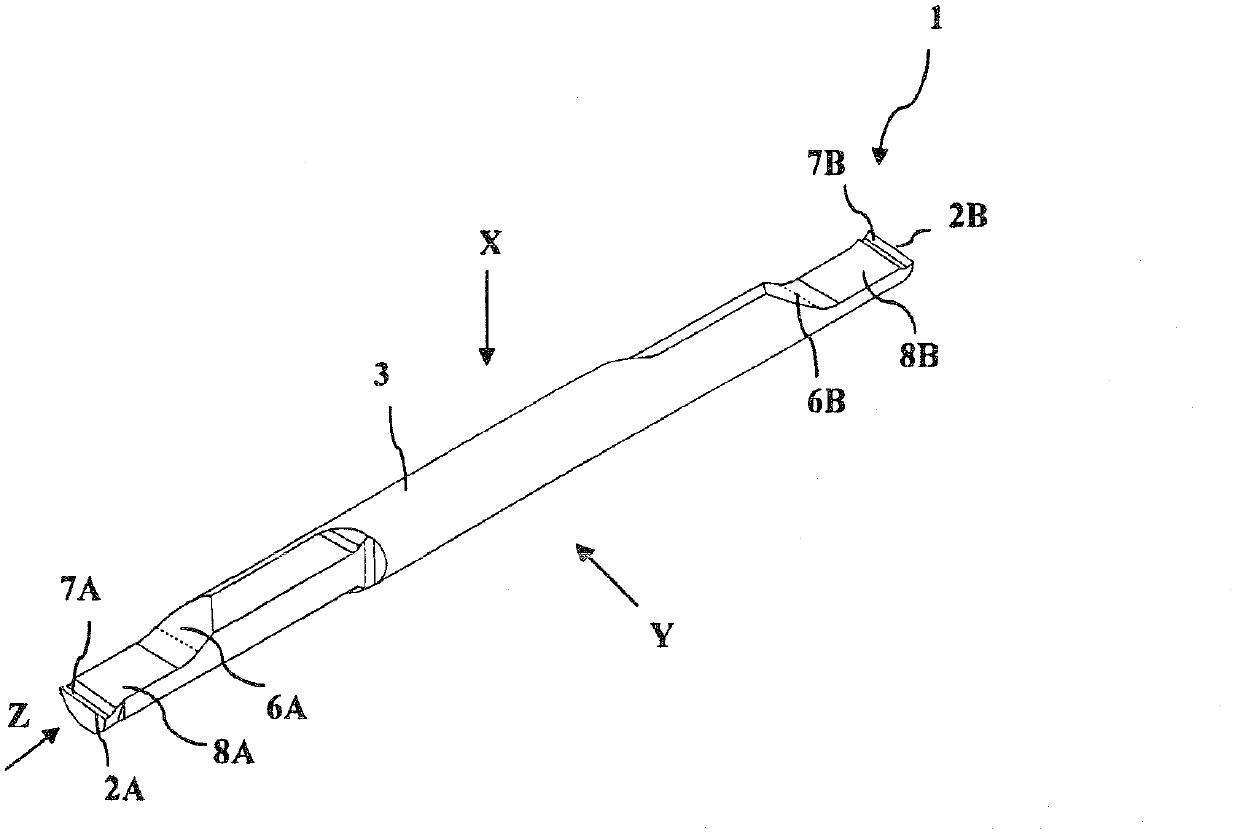
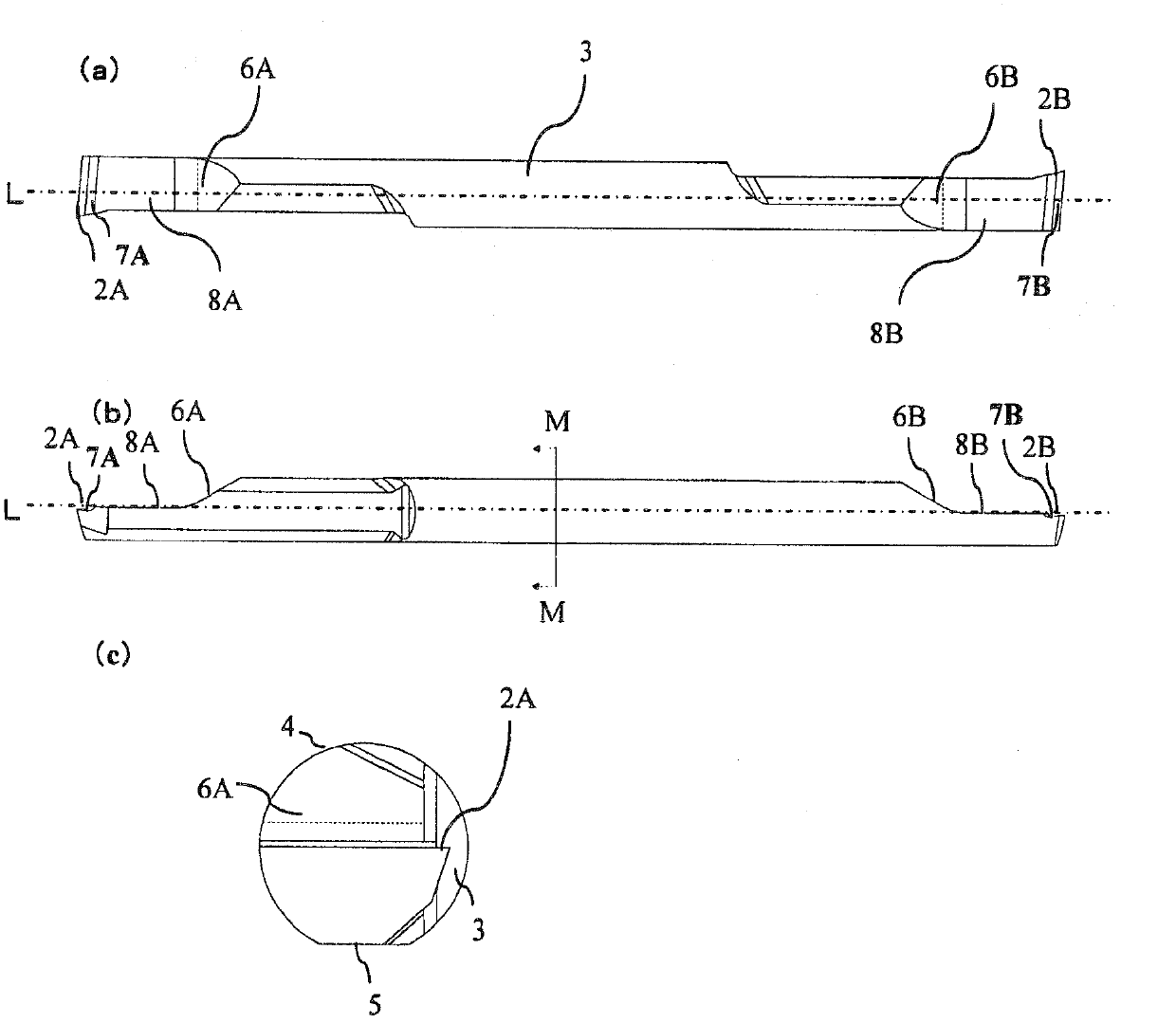
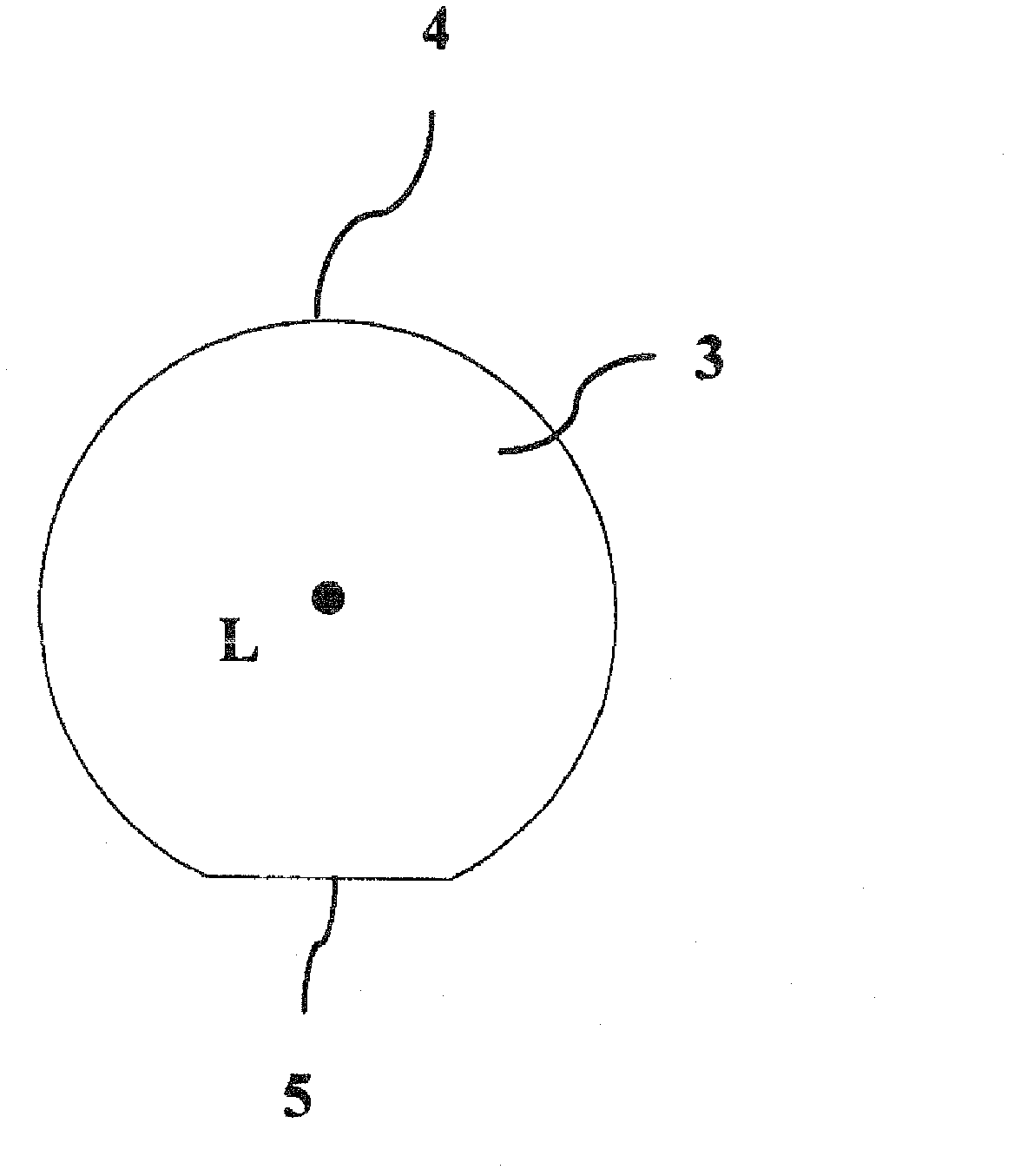
[0031] Below, use Figure 1 to Figure 6 Next, a cutting tool T for machining an inner diameter used by attaching the insert 1 according to one embodiment of the present invention to the holder 10 will be described. figure 1 It is a brief perspective view of insert 1, figure 2 It is viewed from (a) X direction (top view direction) figure 1 (b) is a side view viewed from the Y direction (side view direction), (c) is an end view obtained from the Z direction (front end direction), image 3 yes figure 2 (a) M-M sectional view. and, Figure 4 is a schematic perspective view of a cutting tool T with an insert 1 attached to a tool holder 10, Figure 5 It is viewed from (a) X direction (top view direction) Figure 4 (b) is a side view viewed from the Y direction (side view direction), (c) is an end view obtained from the Z direction (tip direction), Image 6 yes Figure 5 (b) N-N sectional view.

[0032] exist figure 1 Among them, the insert 1 is composed of a rod-shaped b...


PUM


Abstract

Provided is an insert that has good positioning precision and sufficient rigidity. Said insert is rod-shaped and has: a shank part; cutting blades formed on both sides of the shank part; and raised surfaces that are positioned between the cutting blades and the shank part and bulge such that parts farther away from the cutting blades are progressively closer to the outer surface of the shank part. In a side view, the rake face of the cutting blade on one side and the raised surface on the other side are disposed in the same direction with respect to the axis of rotation of the shank part.

Description

technical field [0001] The present invention relates to an insert, a tool holder using the insert, and a cutting tool using the insert and the tool holder. Background technique [0002] Conventionally, as a cutting tool used for internal grooving or thread cutting, it is known that a substantially rod-shaped insert (hereinafter, simply referred to as an insert) having cutting edges at both ends is inserted into a hole of a holder, and The structure is locked and fixed by bolts. [0003] For example, Patent Document 1 discloses a cutting tool in which one end of a substantially rod-shaped insert having cutting edges at both ends is inserted into a hole in a holder, and the relief surface on the side of one end of the insert is aligned with the holder. The axial positioning of the insert is performed by abutting against the inner positioning member. [0004] However, although such inserts are axially positioned with relatively high accuracy, the repeatability of the core hei...

Claims


Application Information

Patent Timeline
Patent Type & Authority Applications(China)
IPC IPC(8): B23B27/14B23B27/16
CPCB23B29/043B23B2270/14B23B27/007B23B27/045B23B2250/16Y10T82/2589Y10T407/2222Y10T407/2262Y10T407/228Y10T407/2284Y10T407/24
Inventor 小林洋司
Owner KYOCERA CORP
Why Eureka
Try Eureka