
Electrical connection box

A technology for electrical junction boxes and electrical components, applied in electrical components, multiple connection components, circuit layout on support structures, etc., and can solve problems such as disconnection, mutual separation, separation, etc.

Active Publication Date: 2012-03-21
YAZAKI CORP
View PDF9 Cites 16 Cited by
  • Summary
  • Abstract
  • Description
  • Claims
  • Application Information

AI Technical Summary

Problems solved by technology

Thus, vibratory movements, for example of a moving vehicle, may cause the cassette blocks 103, 105 to move away from each other along the insertion direction Z, causing the insertion part 104 to separate from the receiving part 106
As a result, not only the cassette blocks 103, 105 may separate from each other, but also the bus bars 108, 109 may separate from each other, thereby breaking the electrical connection between the bus bars 108, 109

Method used


Image

  • Electrical connection box
  • Electrical connection box
  • Electrical connection box

Examples


Embodiment Construction

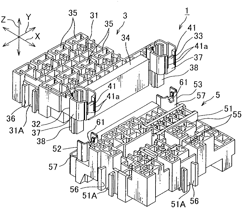
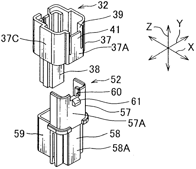
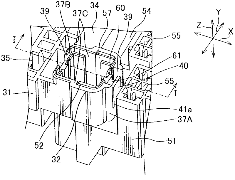
[0027] Refer to the following Figures 1 to 5 An electrical junction box according to one embodiment of the present invention is described.

[0028] The electrical junction box 1 according to the present invention is arranged to be installed in an engine compartment of a motor vehicle in order to supply electric power to various electrical equipment mounted on the motor vehicle. The term electrical junction box used herein is broadly understood as junction box, fuse box and relay box.

[0029] Such as Figures 1 to 5 As shown in , the electrical junction box 1 includes: a plurality of electrical components; a first box block 3 having a pair of first receiving portions 32, 33; a second box block 5 coupled to The first cassette block 3, and has a pair of second receiving portions 52, 53; a plurality of first electric wires wired at the first cassette block 3; a plurality of second electric wires wired at the second cassette block 5 place ; a fuse 8 connected to the first elec...


PUM


Abstract

There is provided a downsized electrical connection box in which the reliability of the mechanical connection between blocks provided in the electrical connection box is improved. The electrical connection box 1 includes a plurality of electric components, a first block 3 mounted with the electric components and a second block mounted with the electric components. The first block 3 includes a tubular-shaped first member 32, 33 projecting towards the second block 5. The second block 5 includes a second member 52, 53 arranged to be slidably inserted into the first member. The first and the second blocks 3, 5 are coupled to each other by slidably inserting the second member 52, 53 into the first member 32, 33. At least one electric component 8 of the plurality of electric components is received inside the first and the second members 32, 52, 33, 53.

Description

[0001] Cross application of related applications [0002] The priority application Japanese Patent Application No. 2010-190794 on which this patent application is based is hereby incorporated by reference. technical field [0003] The present invention generally relates to an electrical junction box to be installed in the engine compartment of a motor vehicle. Background technique [0004] A variety of electrical equipment is installed in a motor vehicle as a moving object. In order to supply power to those electrical equipment, an electrical junction box is installed in a vehicle at a suitable position between a power source and the electrical equipment. Such electrical junction boxes are mounted with electrical components such as connectors, relays, and fuses. [0005] The term electrical junction box as used herein is also referred to as a junction block, fuse block or relay box. [0006] FIG. 6 is a perspective view of a conventional electrical junction box 101 . FIG...

Claims


Application Information

Patent Timeline
Patent Type & Authority Applications(China)
IPC IPC(8): H02G3/16
CPCH05K7/026
Inventor 佐藤尚史山本正树中村和明萩原正之
Owner YAZAKI CORP
Learn More