Reconfigurable modular robot
A robot and modular technology, applied in the field of robotics, can solve problems such as hardware design problems
- Summary
- Abstract
- Description
- Claims
- Application Information
AI Technical Summary
Problems solved by technology
Method used
Image
Examples
Embodiment 1
[0035] Example 1: Reconfigurable module
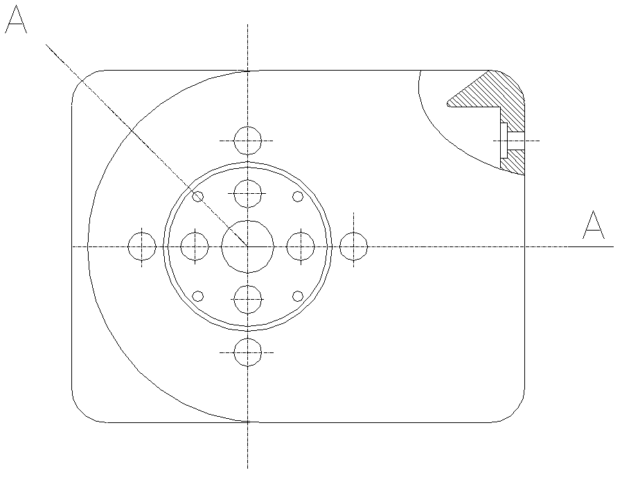
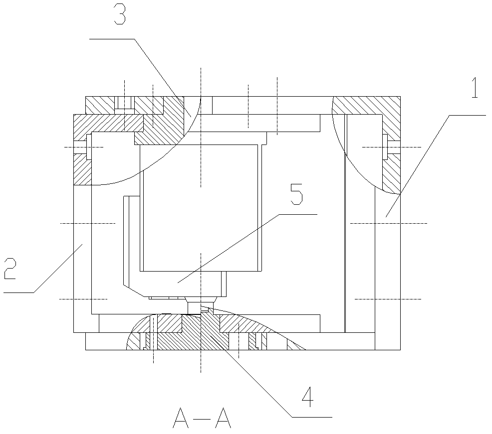
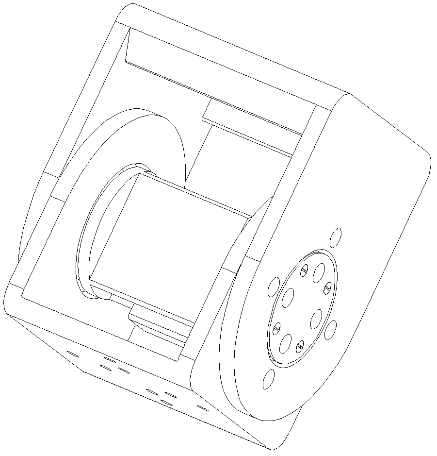
[0036] Such as Figure 1 to Figure 6 As shown, the reconstruction module is a 100*100*128 rectangular parallelepiped, including a U-shaped outer frame 1, a U-shaped inner frame 2. One side of the U-shaped outer frame has a set of bolts fixed to the rudder frame The other side of the hole 6 and a positioning hole 7 is provided with an outer frame bearing hole 8 connected with the bearing installed on the inner frame coupling member, and a set of module combination connecting holes 9 are respectively provided on both sides and bottom side of the U-shaped outer frame. The U-shaped inner frame has an inner frame bearing hole 10 connected to the bearing of the rudder frame 3 on one side that matches the U-shaped outer frame with bolt holes, and the other side has an inner frame bearing hole 10 coaxial with the outer frame bearing hole for passing through the inner frame. The matching hole 11 of the inner pillow block of the frame coupling 4 a...
Embodiment 2
[0038] Embodiment 2: Reconstructing modular robot 1
[0039] Such as Figure 8 to Figure 11 As shown, the bottom side of the U-shaped outer frame of the two modules are connected to form a straight line. The two U-shaped outer frames form the main body, and the two U-shaped inner frames can rotate 360° continuously (clockwise rotation means rightward rotation, counterclockwise rotation To go left), perform special wheeled exercises, take the right behavior as an example, Figure 8 For the movement to start, Picture 9 For the state when turning an acute angle, Picture 10 For the state when turning an obtuse angle, Picture 11 In order to turn 180°, that is, the state of half a circle, rotate half a circle again to return to the initial position and proceed to the next step, so that the cycle achieves the purpose of right travel.
Embodiment 3
[0040] Embodiment 3: Reconstruction module robot 2 (example of combination of four reconfiguration modules)
[0041] Such as Figure 12 to Figure 15 Shown is the mobile camera robot reconstructed from the four modules of reconstruction module I, II, III, and IV. The U-shaped outer frame side C1 of the reconstruction module I and the reconstruction Module The bottom side A of the U-shaped outer frame of Ⅱ is fixedly connected, the U-shaped inner frame C2 of the reconstruction module Ⅱ is fixedly connected with the U-shaped inner frame C2 of the reconstruction module Ⅲ, and the bottom side A of the U-shaped outer frame of the reconstruction module Ⅲ is connected to the heavy The inner frame C2 of the structural module IV is connected, and a camera (not shown in the figure) is installed in the middle of the bottom side of the U-shaped outer frame of the reconstruction module IV. in Picture 12 In the state of, the robot is in the stage of searching for the target. The rotation of t...
PUM
 Abstract
Description
Claims
Application Information
 - R&D
- Intellectual Property
- Life Sciences
- Materials
- Tech Scout
- Unparalleled Data Quality
- Higher Quality Content
- 60% Fewer Hallucinations
Browse by: Latest US Patents, China's latest patents, Technical Efficacy Thesaurus, Application Domain, Technology Topic, Popular Technical Reports.
© 2025 PatSnap. All rights reserved.Legal|Privacy policy|Modern Slavery Act Transparency Statement|Sitemap|About US| Contact US: help@patsnap.com


