
Reconfigurable modular robot

A robotic and modular technology, applied in the field of robotics, which can solve problems such as hardware design problems

Inactive Publication Date: 2012-03-21
TIANJIN UNIVERSITY OF TECHNOLOGY
View PDF4 Cites 19 Cited by
  • Summary
  • Abstract
  • Description
  • Claims
  • Application Information

AI Technical Summary

Problems solved by technology

[0004] Although after decades of development, the modular reconstruction robot has made great progress in technology, but there are still many problems in hardware design.

Method used


Image

  • Reconfigurable modular robot
  • Reconfigurable modular robot
  • Reconfigurable modular robot

Examples


Embodiment 1

[0037] Example 1: Reconfigurable Modules

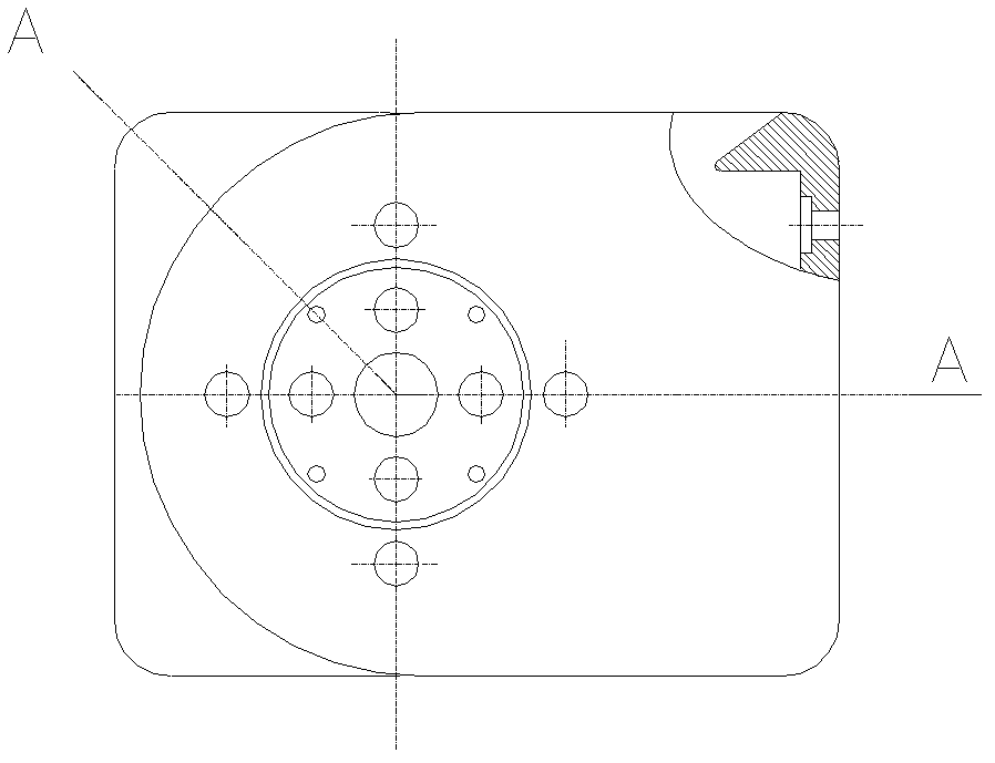
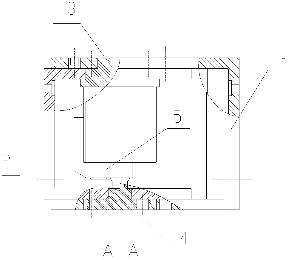
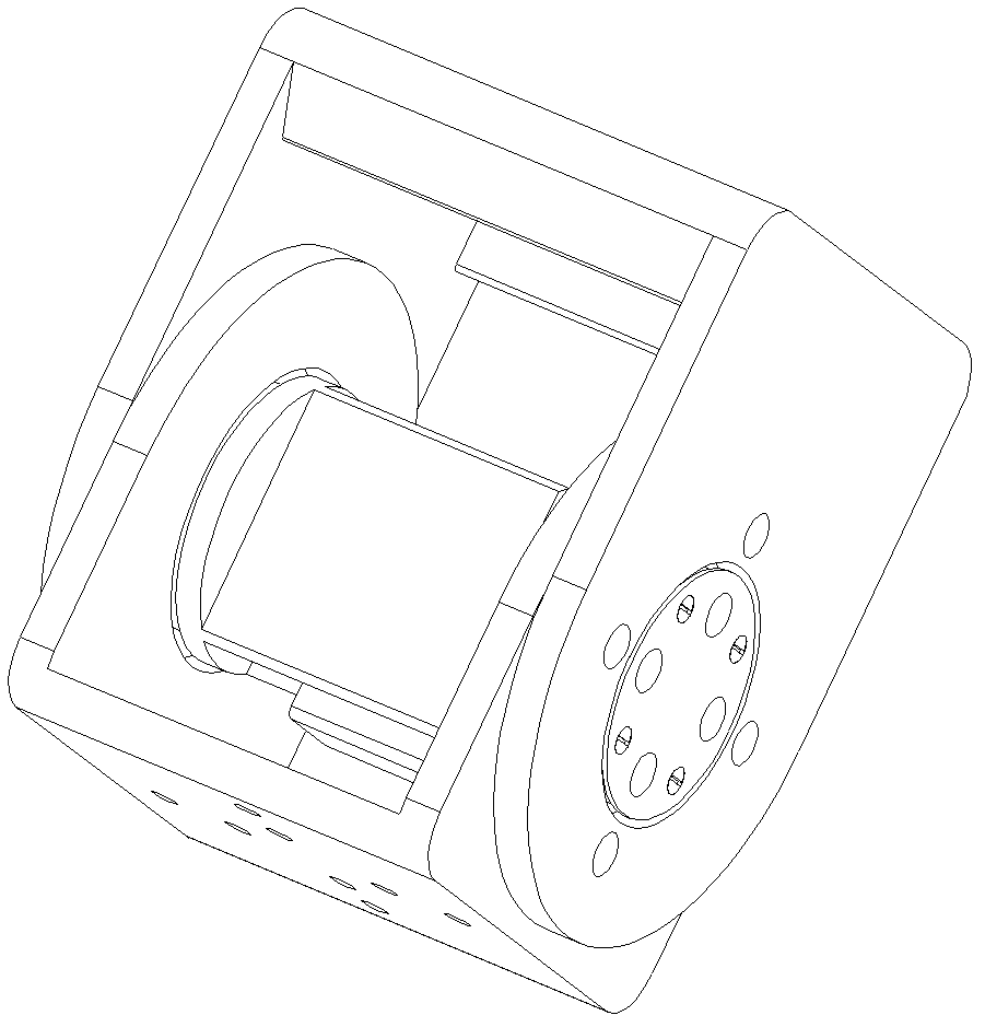
[0038] like Figure 1 to Figure 6 As shown, the reconstruction module is a 100*100*128 cuboid, including a U-shaped outer frame 1, a U-shaped inner frame 2, and one side of the U-shaped outer frame has a set of bolts fixed to the steering gear frame Hole 6 and a positioning hole 7, the other side has the outer frame bearing hole 8 that is connected with the bearing installed on the inner frame coupling shaft, and the two sides and the bottom side of the U-shaped outer frame are respectively provided with a group of module combination connection holes 9. The U-shaped inner frame has the inner frame bearing hole 10 that is connected with the steering gear frame 3 bearings on the side that cooperates with the U-shaped outer frame with the bolt hole surface, and the other side has a coaxial hole with the outer frame bearing hole that is used to pass through the inner frame. The matching holes 11 of the inner side pillow block of the fr...

Embodiment 2

[0040] Example 2: Refactoring Module Robot 1

[0041] like Figure 8 to Figure 11 As shown, the bottom sides of the U-shaped outer frames of the two modules are connected and reconstructed into a straight line. The two U-shaped outer frames form the main body. to go to the left), to perform special wheeled movement, take the right row as an example, Figure 8 for the movement to begin, Figure 9 is the state when turning an acute angle, Figure 10 is the state when turning through an obtuse angle, Figure 11 In order to turn over 180°, that is, the state of half a circle, rotate half a circle again to return to the initial position for the next step forward, and so on to achieve the purpose of going right.

[0042]

Embodiment 3

[0043] Example 3: Refactoring Module Robot 2 (Example of Combination of Four Refactoring Modules)

[0044] like Figure 12 to Figure 15 As shown, it is the mobile camera robot reconstructed by four modules of reconstruction module I, II, III, and IV. The U-shaped outer frame side C1 of reconstruction module I module The bottom side A of the U-shaped outer frame of II is fixedly connected, the U-shaped inner frame C2 of the reconstruction module II is fixedly connected with the U-shaped inner frame C2 of the reconstruction module III, and the bottom side A of the U-shaped outer frame of the reconstruction module III is connected to the heavy The inner frame C2 of the reconstruction module IV is connected, and a camera (not shown in the figure) is installed in the middle of the bottom side of the U-shaped outer frame of the reconstruction module IV. exist Figure 12 In the state of , the robot is in the stage of searching for the target. The rotation of the U-shaped inner f...


PUM


Abstract

The invention relates to a reconfigurable modular robot, which is formed by combining a plurality of reconfigurable modules capable of independently moving, wherein each reconfigurable module comprises a U-shaped outer frame, a U-shaped inner frame, a steering engine frame, an inner frame shaft connecting element and a steering engine, one side of the U-shaped outer frame is connected with the U-shaped inner frame through the steering engine frame, the other side of the U-shaped outer frame is connected with the U-shaped inner frame through the inner frame shaft connecting element, the steering engine is fixedly arranged in the steering engine frame, the inner side of a shaft sleeve of an steering engine shaft at the extending end of the inner frame shaft connecting element is matched with splines of a steering engine output shaft through spline holes, the side surface and the bottom side of the U-shaped outer frame are respectively provided with module combination connecting holes, the U-shaped inner frame is provided with a group of module combination connecting holes at the side surface, a group of module combination inner ring holes are arranged on the inner frame shaft connecting element, and the reconfigurable modules are connected and combined through the module combination connection inner ring holes or outer ring holes or full holes for forming the modular robot. The U-shaped outer frame and the U-shaped inner frame of the single module can realize 360-degree continuous rotation, the moving function is realized, and several modules can be freely assembled.

Description

technical field [0001] The invention belongs to the field of robot technology, in particular to a reconfigurable modular robot. Background technique [0002] A reconfigurable modular robot is a robot that can reconfigure its configuration according to the needs of tasks and changes in the environment. It is generally composed of many one or a limited number of general-purpose modules through connection. There is a unified interface environment between modules, which can be used to transmit force, motion, energy and communication, and reorganize through disconnection operations between modules. Change the overall configuration, expand the form of motion, and complete a variety of motion and operation tasks. Compared with traditional fixed configuration robots, self-reconfigurable robots have the advantages of strong environmental adaptability, low manufacturing cost, self-repair and self-deformation, etc., and can be applied to many different occasions and complete various c...

Claims


Application Information

Patent Timeline
IPC IPC(8): B62D57/02
Inventor 曹燕军葛为民魏璇
Owner TIANJIN UNIVERSITY OF TECHNOLOGY
Learn More