
Automatic rivet pulling mechanism

A riveting and automatic technology, applied in the field of automatic riveting mechanism, can solve problems such as low efficiency, failure to realize automatic production, and inability to detect rivet fastening force, etc., to achieve the effect of solving low efficiency and realizing automatic production

Active Publication Date: 2012-03-21
天津镕思铭科技股份有限公司
View PDF6 Cites 14 Cited by
  • Summary
  • Abstract
  • Description
  • Claims
  • Application Information

AI Technical Summary

Problems solved by technology

However, these two tools require workers to manually insert the rivet core into the back mouth, then perform riveting action, and finally manually remove the waste nails, which does not realize automatic production
In high-density riveting work, it is inefficient and cannot detect the fastening force of rivets
Moreover, since the process of supplying nails requires manual operation, the entire riveting process cannot be mechanized, which brings inconvenience to factory automation.

Method used


Image

  • Automatic rivet pulling mechanism
  • Automatic rivet pulling mechanism
  • Automatic rivet pulling mechanism

Examples


Embodiment Construction

[0014] The automatic blind rivet mechanism of the present invention will be described in further detail below in conjunction with the accompanying drawings.

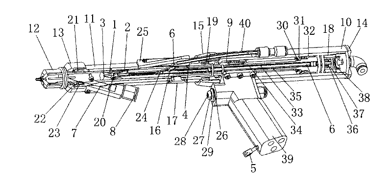
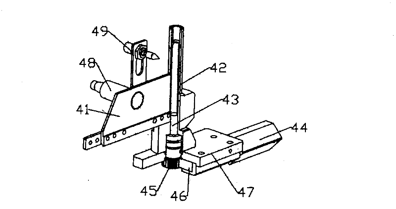
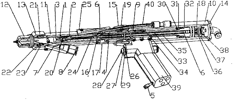
[0015] like figure 1 , figure 2 As shown, an automatic rivet mechanism includes a rivet gun, and the rivet gun includes a gun body with a hollow cavity, a rivet piston 2, a sleeve 4, a sleeve piston 9, a thimble 6, a chuck 1, and a head 12. The rivet piston 2, the sleeve 4, the sleeve piston 9, the thimble 6, and the chuck 1 are installed in the hollow cavity of the gun body, wherein the thimble 6 is connected with the rivet piston 2, and the thimble 6 is installed in the sleeve 4, Sealing head 12 is installed on the front end of gun body, is provided with nail inlet at gun body front end, and gun body rear end is provided with compressed air air inlet, is also provided with hydraulic drive system on gun body, is provided with on gun body Automatic waste nail mechanism, the automatic waste nail mechanism includes a sp...


PUM


Abstract

The invention discloses an automatic rivet pulling mechanism comprising a rivet pulling gun. The rivet pulling gun comprises a gun body with a hollow cavity, and a rivet pulling piston, a sleeve, a sleeve piston, a thimble, a chuck and a seal end which are installed in the cavity. The automatic rivet pulling mechanism is characterized in that an automatic waste rivet discharging mechanism is arranged on the gun body, and comprises a spring piece, a rivet outlet channel, a rivet outlet pipe and compression air for driving the waste rivet to move, the rivet outlet channel is communicated with the rivet outlet pipe, a waste rivet discharging chute is arranged on the sleeve, one end of the spring piece is fixed, and the other end of the spring piece is free and extends into the sleeve by the waste rivet discharging chute, when the spring piece is in natural state, the spring tilts from front to back so as to form a return channel by which a waste rivet enters the rivet outlet channel. According to the automatic rivet pulling mechanism, full-automatic feeding, broken pulling and waste discharging are realized, the problem that manual and semi-automatic rivet pulling are low in efficiency is solved, and the automatic rivet pulling mechanism can be fixed on a mechanical hand so as to realize automatic production.

Description

technical field [0001] The invention relates to the technical field of rivet riveting equipment, in particular to an automatic rivet pulling mechanism. Background technique [0002] Riveting is a commonly used connection method in mechanical connection. Blind rivets are the most widely used standard form rivets, which have many specifications and reliable connections. At present, the blind rivet tools that have been widely used are divided into two categories: manual rivet guns and semi-automatic pneumatic rivet guns. These two types of tools use the lever labor-saving mechanism and compressed air to provide the pulling force to break the rivet, so that pulling the rivet is relatively labor-saving. However, these two tools all require workers to manually insert the core of the rivet into the counter mouth, then perform the riveting action, and finally manually remove the waste nails, which does not realize automatic production. In high-density riveting work, it is ineffic...

Claims


Application Information

Patent Timeline
Patent Type & Authority Applications(China)
IPC IPC(8): B21J15/38
CPCB21J15/043B21J15/105
Inventor 张绍鹏刘士营刘喜双李宝山王洪欣张超文刘吉龙
Owner 天津镕思铭科技股份有限公司
Learn More