
Wafer transfer method and device

A technology for conveying devices and wafers, which is applied in the direction of conveyor objects, transportation and packaging, etc., can solve problems such as fragmentation, achieve the effects of reducing fragmentation rate, improving stability and safety, and saving costs

Inactive Publication Date: 2012-03-14
CSMC TECH FAB1 +1
View PDF7 Cites 16 Cited by
  • Summary
  • Abstract
  • Description
  • Claims
  • Application Information

AI Technical Summary

Problems solved by technology

[0005] In view of this, it is necessary to provide a wafer transfer method that prevents wafer fragmentation for the problem of fragmentation caused by deviation from the designated position during the above-mentioned wafer transfer.

Method used


Image

  • Wafer transfer method and device
  • Wafer transfer method and device
  • Wafer transfer method and device

Examples


Embodiment Construction

[0036] The specific implementation manners of the present invention will be described in detail below in conjunction with the accompanying drawings.

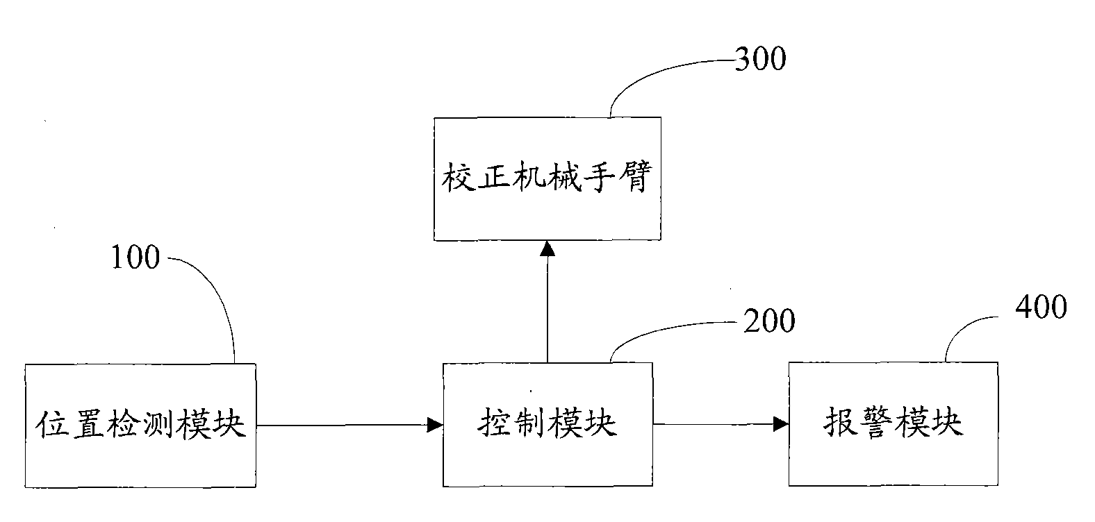
[0037] figure 1 It is a structural schematic diagram of a wafer transfer device in an embodiment. The device includes: a position detection module 100 , a control module 200 , a calibration robot arm 300 and an alarm module 400 .

[0038] The position detection module 100 is used to detect whether the wafer deviates from a specified position, and transmit the detection result to the control module 200 .

[0039] In this embodiment, the designated position is the position where the wafer is carried on the wafer storage and lifting device.

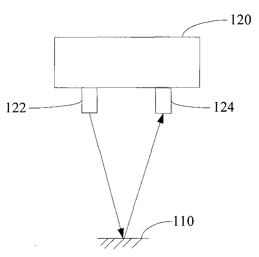
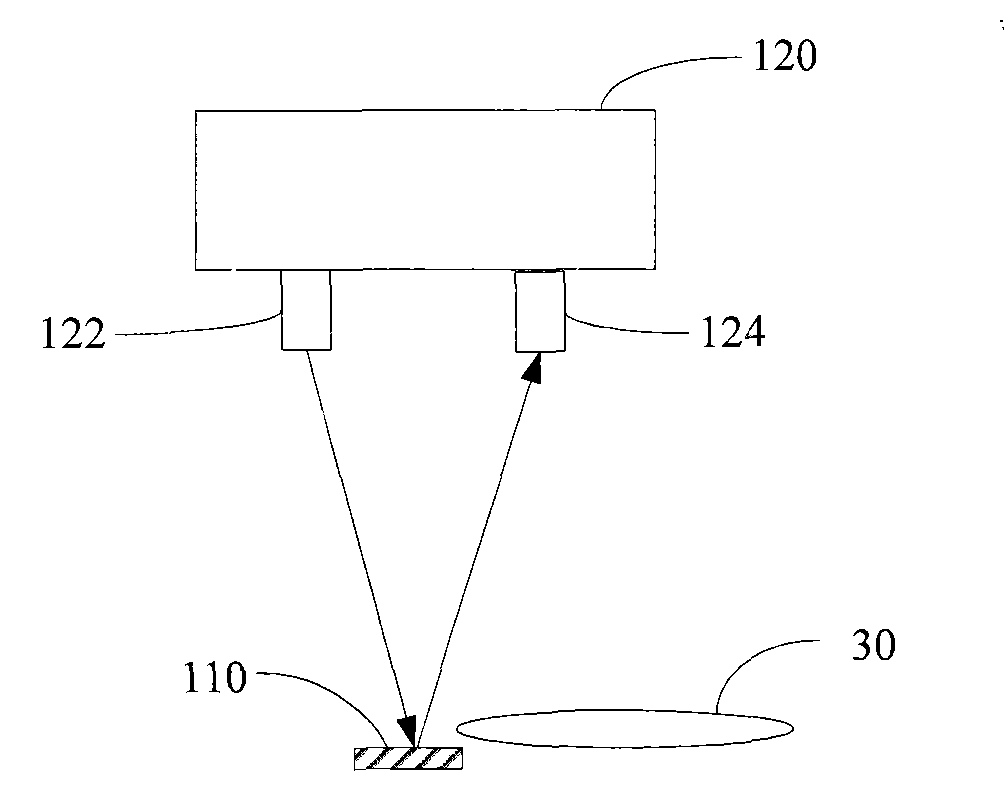
[0040] figure 2 is a structural diagram of the position detection module 100 in an embodiment. In this embodiment, the position detection module 100 includes at least 3 groups of detection optical paths. The detection optical paths are arranged on the edge of the specified position, and ...


PUM


Abstract

The invention relates to a wafer transfer method and device. The method comprises the following steps of: detecting whether a wafer deviates from a designated position; and stopping transferring the wafer when the wafer deviates from the designated position. According to the invention, before the wafer is transferred, whether the wafer deviates from the designated position is detected, and when the wafer deviates from the designated position, a wafer storing and lifting device is stopped transferring the wafer, thereby avoiding the problem of wafer fragment because the wafer deviating from the designated position is continued to be transferred, further improving the stability and safety of wafer transfer, reducing the fragment percent and greatly saving cost.

Description

【Technical field】 [0001] The invention relates to a semiconductor wafer manufacturing process, in particular to a wafer transfer method and device. 【Background technique】 [0002] During the semiconductor manufacturing process, the wafer storage lifting device in the wafer transfer chamber is responsible for the transfer and storage of the wafer. The wafers are transported to the designated position of the wafer storage lifting device for transport and storage. [0003] When the wafer storage and lifting device transfers the wafer, the wafer must be in the designated position before it can be carried out. However, when the wafer is transferred to the wafer storage and lifting device, due to reasons such as machine instability and vibration, the wafer will deviate from the designated position (wafer boat) of the wafer storage and lifting device. When the position of the wafer deviates, if it is not found in time, the wafer storage and lifting device will continue to move up...

Claims


Application Information

Patent Timeline
Patent Type & Authority Applications(China)
IPC IPC(8): H01L21/677
Inventor 毕磊
Owner CSMC TECH FAB1
Learn More