Fuel supply system

A fuel supply system and fuel technology, applied in the direction of the charging system, fuel injection device, fuel air filter, etc., can solve the problem of no additional fuel distribution conduit installation, etc., to achieve simple and cost-saving, simple and low-manufacturing Effect

Inactive Publication Date: 2014-07-02
MAGNA STEYR FAHRZEUGTECHN
View PDF4 Cites 0 Cited by
  • Summary
  • Abstract
  • Description
  • Claims
  • Application Information

AI Technical Summary

Problems solved by technology

The problem here is that, due to manufacturing space constraints, there is often not enough space in modern car engines for an additional fuel distribution duct to be mounted on the aspirator
Since the engine hood is often located in these areas, it is already disadvantageous that only the fuel distribution duct is installed above the air filter box

Method used


Image

  • Fuel supply system
  • Fuel supply system
  • Fuel supply system

Examples


Embodiment Construction

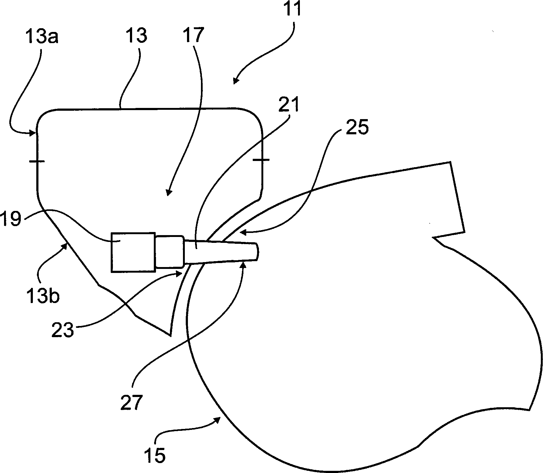
[0023] attached figure 1 Components of a fuel supply system are shown, which supply an internal combustion engine (not shown) with a combustible mixture from intake air and fuel. An air filter module or air filter box 11 with a housing 13 and a filter element, not shown, arranged in the housing 13 for cleaning the intake air is attached to the suction device 15 via a holding device, not shown. , the intake device 15 conveys the intake air purified by the filter element to the cylinders of the internal combustion engine.

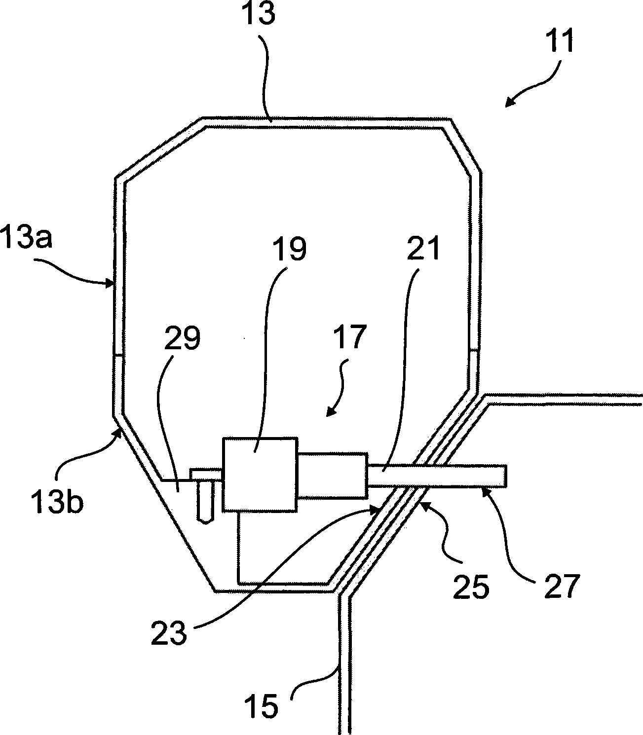
[0024] as attached figure 2 As shown, the air filter housing 13 is divided into an upper part 13a and a lower part 13b, wherein the fuel injection device 17 is integrated in the lower part 13b. The fuel injection device 17 is used to inject fuel 17 into the air intake device 15 to generate a combustible gas / fuel mixture. The fuel injection device 17 comprises a fuel distribution line 19 and a plurality of injection nozzles 21 connected to the fuel distrib...


PUM


Abstract

A fuel supply system for an internal combustion engine having: an air filter for purifying intake air, the air filter comprising a housing and a filter element; an intake air for delivering the purified intake air to a combustion chamber of an internal combustion engine and a fuel injection device comprising a container for fuel under pressure, in particular a fuel distribution conduit, and a plurality of injection nozzles connected to the container. The fuel injection system is integrated into the air filter.

Description

technical field [0001] The invention relates to a fuel supply system for an internal combustion engine, comprising: an air filter for purifying intake air, the air filter comprising a housing and a filter element; chamber suction means; and fuel injection means comprising a container, in particular a fuel distribution conduit, for fuel under pressure, and a plurality of injection nozzles connected to the container. Background technique [0002] As a result of the fuel injection, a combustible gas or fuel mixture is produced in the intake system, which is finally combusted in the combustion chamber of the internal combustion engine. Usually, each engine cylinder, each combustion chamber of the internal combustion engine is likewise provided with its own injection nozzle. The entire reservoir of all cylinders serves as a buffer for the injected fuel, which is placed under pressure by the entire fuel pump of likewise all cylinders. Such containers are also known as fuel distr...

Claims


Application Information

Patent Timeline
Patent Type & Authority Patents(China)
IPC IPC(8): F02M61/14F02M57/00F02M35/02F02M35/10F02D19/06
CPCF02M35/10085F02M35/10216
Inventor F·格罗特M·鲁道夫W·席姆普
Owner MAGNA STEYR FAHRZEUGTECHN
Why Eureka
Try Eureka