Photobioreactor and photobiology culture system
A photobioreactor and photobiological cultivation technology, applied in the field of photobiological cultivation, can solve the problems of large power consumption and poor aeration effect, achieve the effects of convenient cleaning and harvesting, and improve the efficiency of light receiving
- Summary
- Abstract
- Description
- Claims
- Application Information
AI Technical Summary
Problems solved by technology
Method used
Image
Examples
Embodiment 1
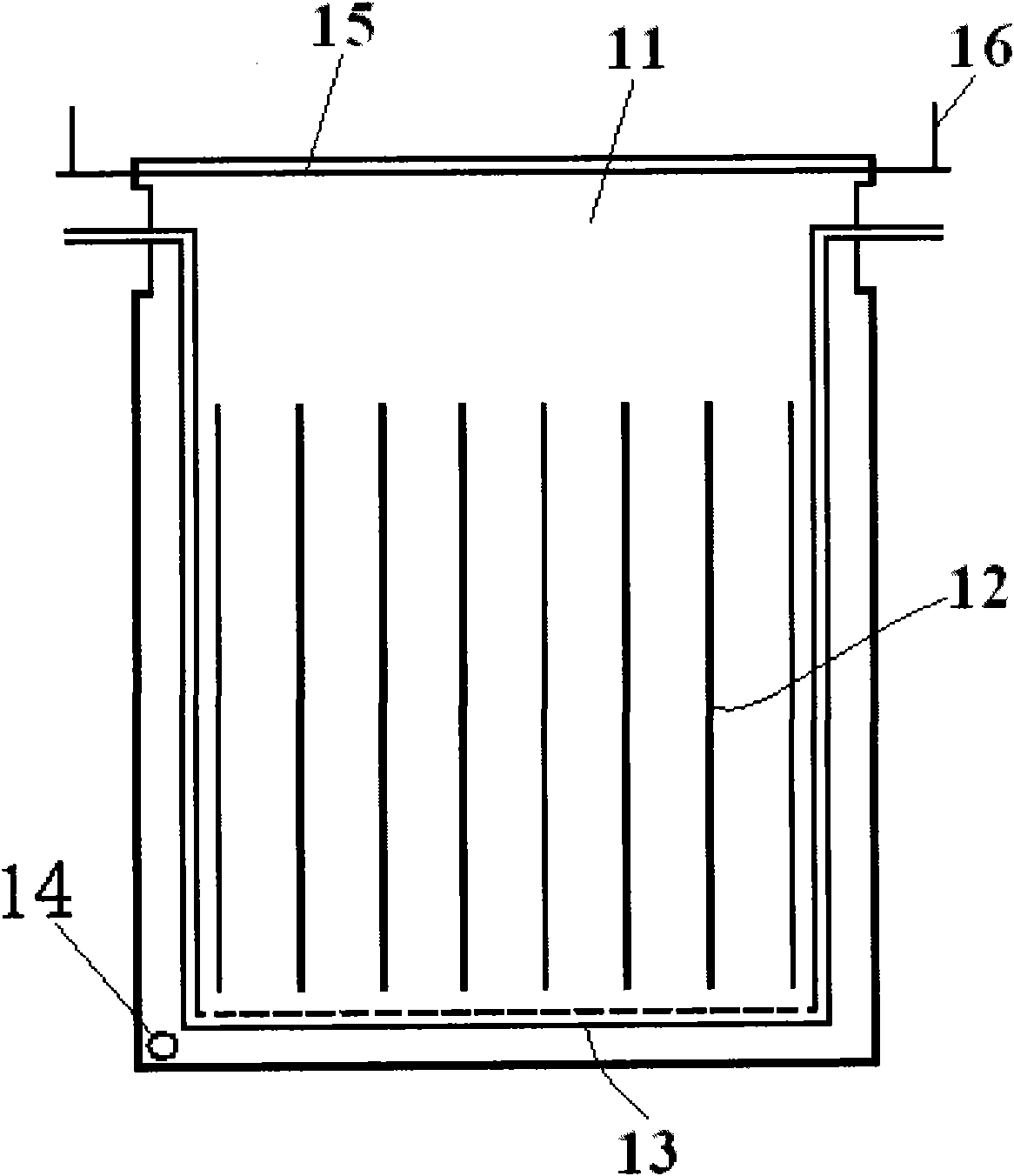
[0042] The photobioreactor provided by Embodiment 1 of the present invention has a structure such as image 3 As shown, it includes: a flexible film 11, a linear isolation belt 12, an aeration device 13, a liquid inlet and outlet 14, and a suspension member composed of a suspension rod 15 and a suspension cable 16.
[0043] The above-mentioned flexible film 11 can be any transparent or translucent film such as polyethylene PE film, polyvinyl chloride PVC film, polyurethane PU film; and at least one side of the films on both sides of the photobioreactor is a transparent or translucent material; The sealing edges of the above-mentioned flexible film 11 are sealed by heat sealing or by sealing clips.
[0044] That is, the lower part and both side edges of the two flexible films 11 can be heat-sealed or clamped with sealing clips to form a fluid-connected bag-like container. It can also be sealed as a cylindrical film with a piece of flexible film, or an integrated cylindrical fi...
Embodiment 2
[0051] The photobioreactor provided by the second embodiment of the present invention has a structure such as Figure 4 As shown, it includes: a flexible film 21, a linear isolation belt 22, an aeration device 23, a liquid inlet and outlet 24, and a suspension member composed of a suspension rod 25 and a suspension cable 26.
[0052] It differs from the photobioreactor provided in Example 1 in that its aeration device 23 is a straight air pipe, and its inlets and outlets are located at the bottom. In the first embodiment, the aeration device 23 is a U-pipe ventilation pipe, and its inlet and outlet are located at the upper part of the photobioreactor.
[0053] A number of vertical linear isolation strips 22 are arranged between the flexible films 21 . The difference from Embodiment 1 is that the linear isolation strip 22 can pass through at least one pair of columns 101, 102 (see Figure 9 , formed at positions on the front and rear sides corresponding to the linear isolatio...
Embodiment 3
[0058] The photobioreactor provided by Embodiment 3 of the present invention has a structure such as Figure 5 As shown, it includes: a flexible film 31 , a linear isolation belt 32 , an aeration device 33 , a liquid inlet and outlet 34 , and a suspension member composed of a suspension hole 35 .
[0059] It differs from the photobioreactor provided in Example 1 in that its suspension member is a suspension hole 35 . The suspension of the reactor is directly realized through the suspension hole 35 . As shown in the figure, the upper part of the flexible film 31 is pointed, and a hanging hole is provided at the pointed corner.
[0060] The rest of the structure of the photobioreactor is the same as that of Embodiment 1, and will not be repeated here.
PUM
| Property | Measurement | Unit |
|---|---|---|
| diameter | aaaaa | aaaaa |
Abstract
Description
Claims
Application Information
 - R&D
- Intellectual Property
- Life Sciences
- Materials
- Tech Scout
- Unparalleled Data Quality
- Higher Quality Content
- 60% Fewer Hallucinations
Browse by: Latest US Patents, China's latest patents, Technical Efficacy Thesaurus, Application Domain, Technology Topic, Popular Technical Reports.
© 2025 PatSnap. All rights reserved.Legal|Privacy policy|Modern Slavery Act Transparency Statement|Sitemap|About US| Contact US: help@patsnap.com


