
Pressing part structure for bent plate of crane

A crane and bending plate technology, applied in metal processing equipment, forming tools, manufacturing tools, etc., to achieve the effect of increasing overall strength, ensuring bearing strength, and prolonging service life

Inactive Publication Date: 2012-03-07
无锡泰立特科技有限公司
View PDF0 Cites 1 Cited by
  • Summary
  • Abstract
  • Description
  • Claims
  • Application Information

AI Technical Summary

Problems solved by technology

[0003] In view of the above-mentioned defects in the existing mold equipment for the deformation of the crane tailstock parts, the present invention provides a structure of the bending plate pressing part of the crane, which can prevent the pressing process Due to the unbalanced force, the lower mold splits and moves, ensuring the bearing strength of the mold and prolonging the service life of the mold

Method used


Image

  • Pressing part structure for bent plate of crane
  • Pressing part structure for bent plate of crane

Examples


Embodiment Construction

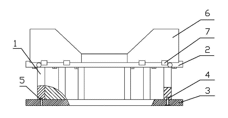
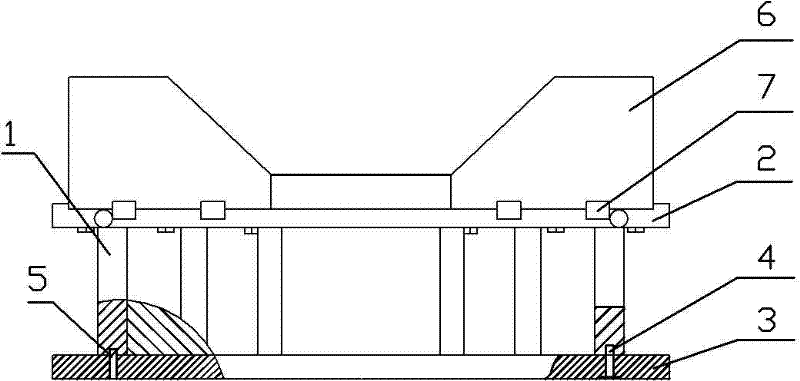
[0008] See figure 1 , the present invention includes a lower mold body 6 and a lower mold base weldment structure, the lower mold base weldment structure includes a base plate 3, a base upper plate 2, and a base 1, and the base plate 3 and the base 1 are installed and fixed by screws 4 and pins 5 , the base 1 and the upper plate 2 of the base are connected by welding, the lower mold body 6 adopts an integral insert, and the welding structure of the lower mold body 6 and the lower mold seat is positioned by eight positioning keys 7 (the other four positioning keys are not shown in the figure) .


PUM


Abstract

The invention provides a pressing part structure for a bent plate of a crane, which can prevent a lower die from separating and reciprocating due to unbalanced stress in a pressing process, thereby ensuring the bearing strength of the die and prolonging the service life of the die. The structure comprises a lower die body and a lower die holder welding part structure, wherein the lower die holder welding part structure comprises a base plate, a base upper plate and a base. The structure is characterized in that: the lower die body is a whole embedded lump; the base plate and the base are mounted and fixed by virtue of bolts and pins; and the base and the base upper plate are connected by virtue of welding.

Description

technical field [0001] The invention relates to a mold device for deformation of a crane tailstock part, in particular to a structure of a bent plate pressing part of a crane. Background technique [0002] Crane tailstock parts are usually bent plate parts, and the manufacture of bent plate parts requires pressing a plate of a certain shape through a deformation die device. At present, the mold equipment used in China for the deformation of crane tailstock parts has a structure: the workpiece is asymmetrical, the spliced ​​lower mold is split, and the welded parts of the lower mold seat are designed using the conventional design method of welding and assembly sequence from bottom to top, that is, the base plate 1. The base is welded and then connected with the upper plate of the base by screws. This structure has the disadvantages that the unbalanced force is easy to cause the split of the lower mold, and the bearing strength of the mold is weak, which affects the service li...

Claims


Application Information

Patent Timeline
Patent Type & Authority Applications(China)
IPC IPC(8): B21D37/10B21D5/06
Inventor 吴坚
Owner 无锡泰立特科技有限公司
Learn More