
Wireless two-way transmission of serial data signals between an electronic device and a power meter

A technology for electronic equipment and energy meters, applied in the direction of near-field transmission systems using capacitive coupling, transmission systems, near-field transmission systems, etc.

Inactive Publication Date: 2014-03-26
ITRON FRANCE
View PDF6 Cites 0 Cited by
  • Summary
  • Abstract
  • Description
  • Claims
  • Application Information

AI Technical Summary

Problems solved by technology

As with capacitive coupling described above, data exchange via inductive coupling can only transfer changed signals

Method used

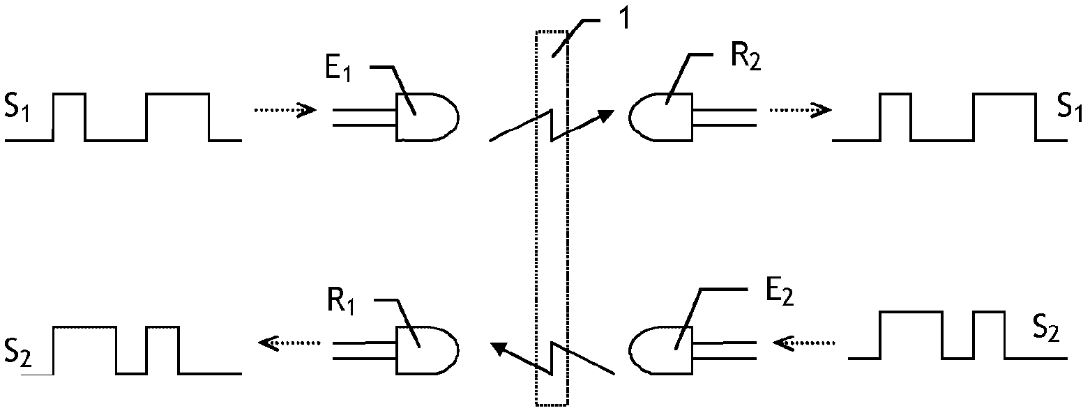
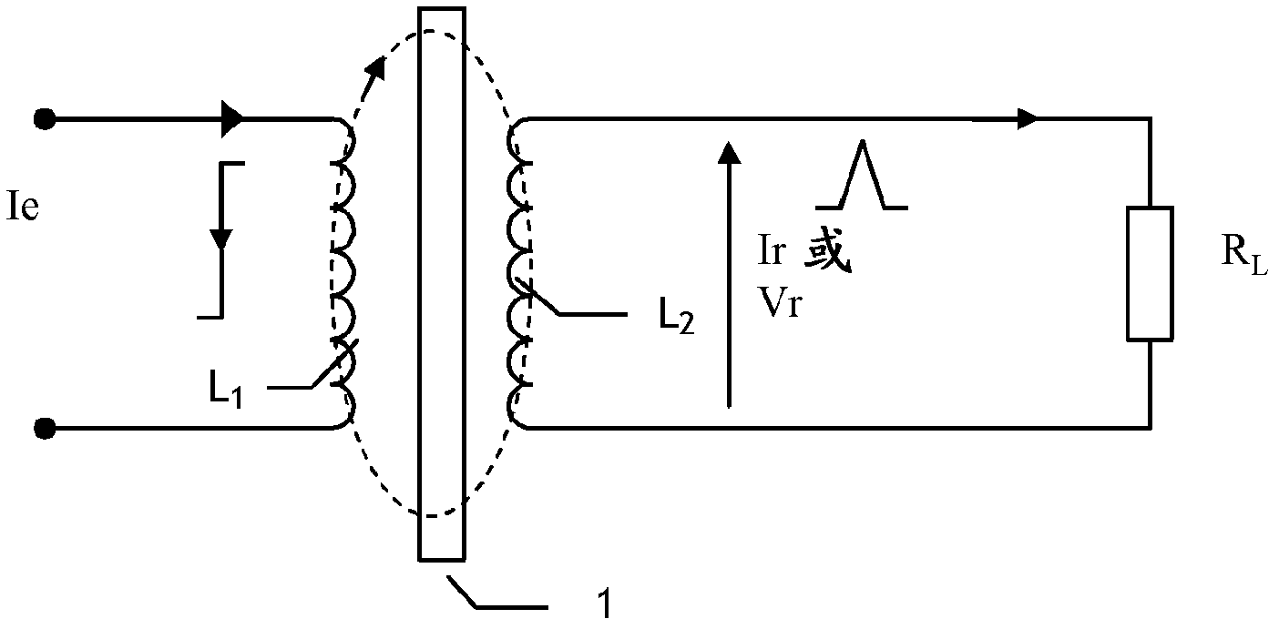

Image

  • Wireless two-way transmission of serial data signals between an electronic device and a power meter
  • Wireless two-way transmission of serial data signals between an electronic device and a power meter
  • Wireless two-way transmission of serial data signals between an electronic device and a power meter

Examples


Embodiment Construction

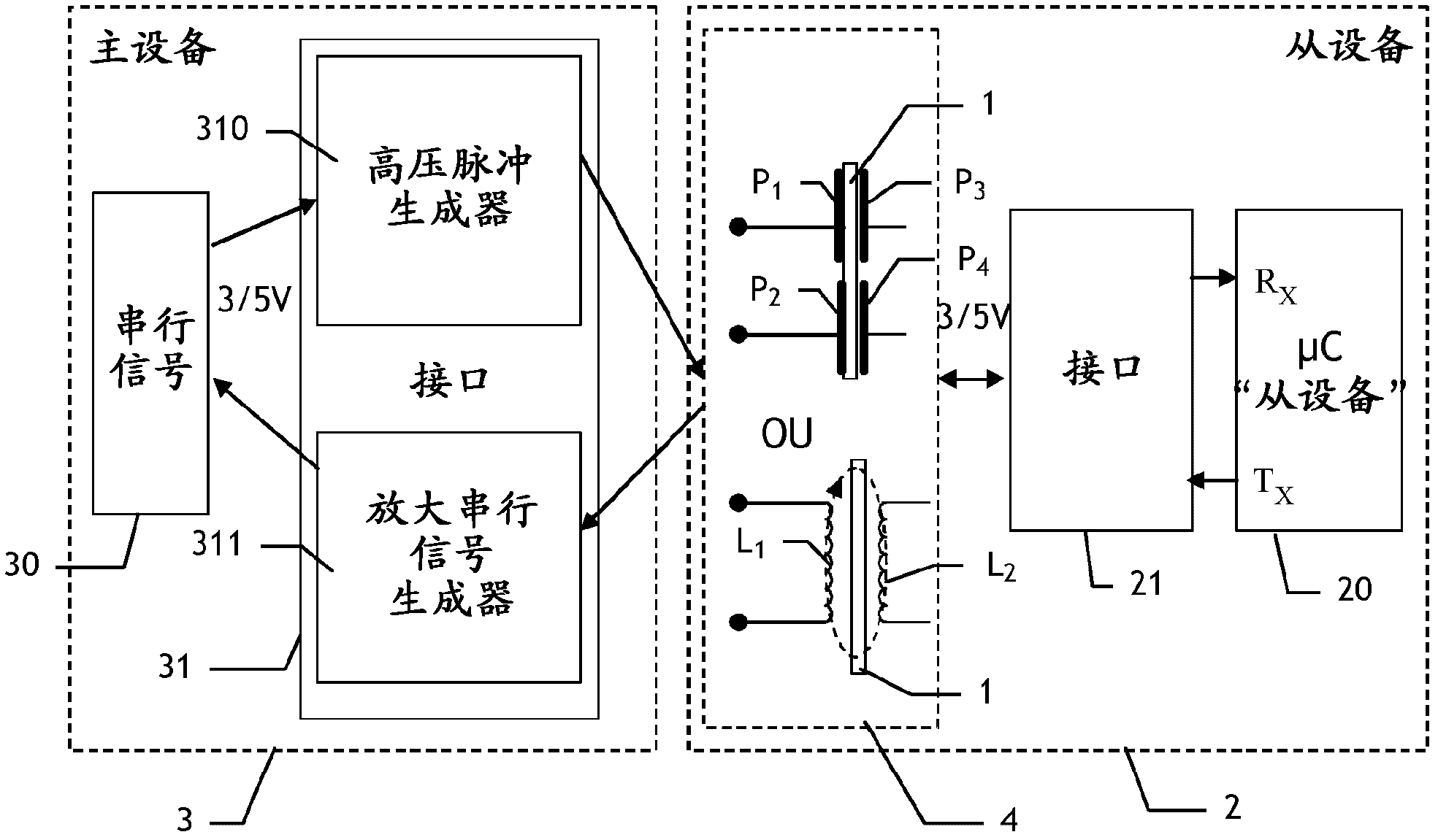
[0034] figure 2 The components required for bi-directional serial data communication between a "slave" device 2 constituted by an energy meter comprising a microcontroller 20 and a "master" electronic device 3, eg a test device, are shown in simplified block diagram form. Recall that the signals to be exchanged between the "master" device 3 and the "slave" device 2 are signals of the serial type, eg asynchronous signals in the RS232 standard format. Such serial signals have two fixed levels (typically 0 / 5 volts or 0 / 3 volts for battery powered devices) and they represent a "0" or "1" bit string.

[0035] Bidirectional data transmission is achieved by capacitive or inductive type electromagnetic coupling. figure 2 This electromagnetic coupling is schematically shown by the dashed box 4 in .

[0036] Upstream of the microcontroller 20 in the receiving direction are also provided two interfaces for performing the functions that will be explained below, namely a first interface ...


PUM


Abstract

The system has a rectangular two-way electromagnetic coupling unit (4), outputting pulses that are output to a serial input port (Rx) of a microcontroller (20), to exchange serial data signals between a master electronic device (3) and a slave power meter (2). The microcontroller is programmed so that each pulse received at the port generates a break and bits are generated at serial data transmission speed. Value of each bit is equal to that of the preceding bit or equal to the reciprocal of that of the preceding bit if the breaks are not received and are received in meantime, respectively. The two-way electromagnetic coupling unit is chosen from an inductive type electromagnetic coupling unit or a capacitive type electromagnetic coupling unit.

Description

technical field [0001] The present invention relates to very short-distance two-way wireless transmission of serial format data signals between two adjacent electronic devices. Background technique [0002] The transmission of such serial signals between the electrical circuits of an energy meter, such as a water, gas or electricity meter and referred to hereinafter as a "slave" device, will be described in detail below, and an external "master" electronic device. [0003] The circuit of an energy meter usually consists of a microcontroller with a serial link on its two serial ports, the first port R for receiving serial signals x and port T for sending serial signals x . With the help of this serial link, the microcontroller can exchange serial data with other electronic devices. [0004] This serial data exchange may be required at different stages during the life of the energy meter, and in particular: [0005] - at various stages during manufacture, before the variou...

Claims


Application Information

Patent Timeline
Patent Type & Authority Patents(China)
IPC IPC(8): H04L25/02H04B5/00
CPCH04B5/0012H04B5/0031H04L25/0266H04B5/0093H04B5/22H04B5/266H04B5/72
Inventor S·贝尔图
Owner ITRON FRANCE
Learn More