Precision four-post hydraulic cutting machine

A cutting machine and hydraulic technology, applied in metal processing and other directions, can solve the problems of inability to guarantee the synchronous action of four columns, low cutting pressure, low work efficiency, etc., and achieve the effect of good cutting effect, fast blanking speed and compact structure.

Inactive Publication Date: 2012-02-29
QUZHOU TAIWEI PRECISE MASCH CO LTD
View PDF7 Cites 7 Cited by
  • Summary
  • Abstract
  • Description
  • Claims
  • Application Information

AI Technical Summary

Problems solved by technology

Its disadvantages are: due to the use of a single oil cylinder to drive the four columns to reciprocate up and down, the cutting pressure is small, the work efficiency is low, and the synchronous action of the four columns cannot be guaranteed.

Method used


Image

  • Precision four-post hydraulic cutting machine
  • Precision four-post hydraulic cutting machine
  • Precision four-post hydraulic cutting machine

Examples


Embodiment 1

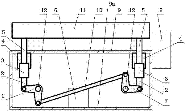
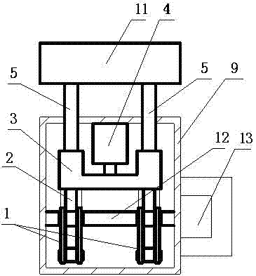
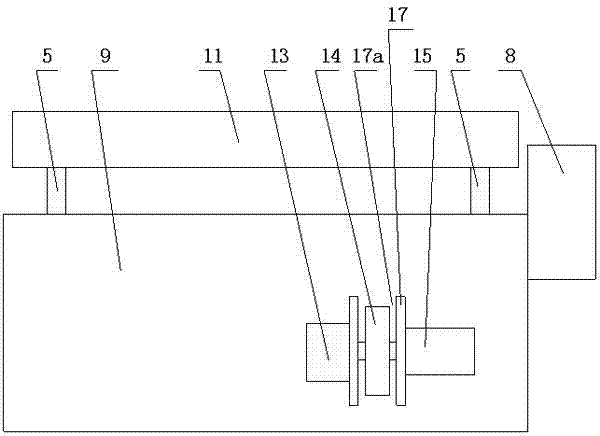
[0015] Embodiment 1: refer to Figure 1~3 . The precision four-column hydraulic cutting machine includes a body 9 containing an oil tank 9a, a pressure back 11, and columns 5 are installed in the four corner holes of the body 9. The lower ends of the two columns 5 on the left and right sides are fixedly connected with hinge seats 3. The upper ends of the columns 5 are respectively connected to the pressure The lower end of the back 11 is fixedly connected, an oil cylinder 4 is arranged between the upper end of the body 9 and the hinge seat 3, the cylinder body of the oil cylinder 4 is fixedly connected with the upper end of the body 9, and the piston rod end is fixedly connected with the hinge seat 3, and the hinge seat in the body 9 3. There is a linkage assembly below. The linkage assembly includes two sets of C-shaped rocker arms 1, C-shaped rocker arms 7, and linkage arms 10. The first C-shaped rocker arm 1 on the left side of the body faces downwards, and the first C-shap...


PUM


Abstract

The invention relates to a precision four-post hydraulic cutting machine, which comprises a machine body containing an oil tank, a pressure back and upright posts arranged in four corner holes of the machine body; the lower ends of two upright posts at the left and right sides are connected with a hinge seat, and the upper ends of the upright posts are fixedly connected with the lower end of the pressure back respectively; a cylinder is arranged between the upper end of the machine body and the hinge seat, the cylinder body of the cylinder is fixedly connected with the upper end of the machine body, and a piston rod of the cylinder is fixedly connected with the hinge seat; a linkage assembly is arranged below the hinge seat in the machine body; the linkage assembly comprises two groups of C-shaped rocker arms and linkage arms; the opening of the first C-shaped rocker arm positioned at the left side of the machine body is downward, the middle part of the first C-shaped rocker arm is hinged with the machine body, and the left end of the first C-shaped rocker arm is hinged with the hinge seat of the left side in the machine body; the opening of the second C-shaped rocker arm positioned at the right side of the machine body is upward, the middle part of the second C-shaped rocker arm is hinged with the machine body, and the right end of the second C-shaped rocker arm is hinged with the hinge seat of the right side in the machine body; and the right end of the first C-shaped rocker arm is in transmission connection with the left end of the second C-shaped rocker arm through the linkage arms.

Description

[0001] technical field [0002] The invention relates to a cutting machine, in particular to a precision four-column hydraulic cutting machine. Background technique [0003] There has been a published patent number "200820023802.4", named "plane gantry cutting machine", the plane gantry cutting machine has a body 25, four columns 1, pressure back 2, hydraulic source, oil tank 6, setting switch device 11, locking hand wheel 12 , a small wire rope pulley 27, which is characterized in that the middle part of the shaft seat 24 on both sides is connected with the connecting rod 23, the other end of the connecting rod is connected with the cam 28, the cam is fixed at both ends of the transmission crankshaft 7, and the middle part of the transmission crankshaft is connected with the piston rod below the oil cylinder 3 Connected, the top of the oil cylinder is fixed on the machine body, there is an electromagnetic reversing valve 5 above the fuel tank, and an adjustment hand wheel 1...

Claims


Application Information

Patent Timeline
Patent Type & Authority Applications(China)
IPC IPC(8): B26D5/12
Inventor 张新新
Owner QUZHOU TAIWEI PRECISE MASCH CO LTD
Why Eureka
Try Eureka