
Rolling assembly mechanism and method

An assembly mechanism and rolling wheel technology, applied in positioning devices, metal processing machinery parts, clamping, etc., can solve assembly technical requirements (extrusion bonding force cannot meet drawing requirements, component straightness, flatness, etc. It is not easy to guarantee the position tolerance, there is no suitable fixture and unique process plan, etc., to achieve the effect of excellent rolling effect, simple structure and good consistency

Active Publication Date: 2012-02-22
INNER MONGOLIA NORTH HAULER
View PDF9 Cites 0 Cited by
  • Summary
  • Abstract
  • Description
  • Claims
  • Application Information

AI Technical Summary

Problems solved by technology

[0003] This kind of rolling work is a special process, which is difficult to realize without suitable fixtures and unique process solutions
Thin plate parts are easily deformed in multiple clamping in different processes (machining, assembly, etc.), and the shape and position tolerances such as straightness and flatness of the parts are not easy to guarantee; Position tolerance is also difficult to guarantee; important technical requirements such as the bonding force of the components in the assembly are not easy to achieve and guarantee; usually the precision of the rolling wheel itself and the precision of the rolling movement are not enough, resulting in some assembly technical requirements (extrusion bonding force) of the product not being met drawing requirements

Method used


Image

  • Rolling assembly mechanism and method
  • Rolling assembly mechanism and method
  • Rolling assembly mechanism and method

Examples


Embodiment 1

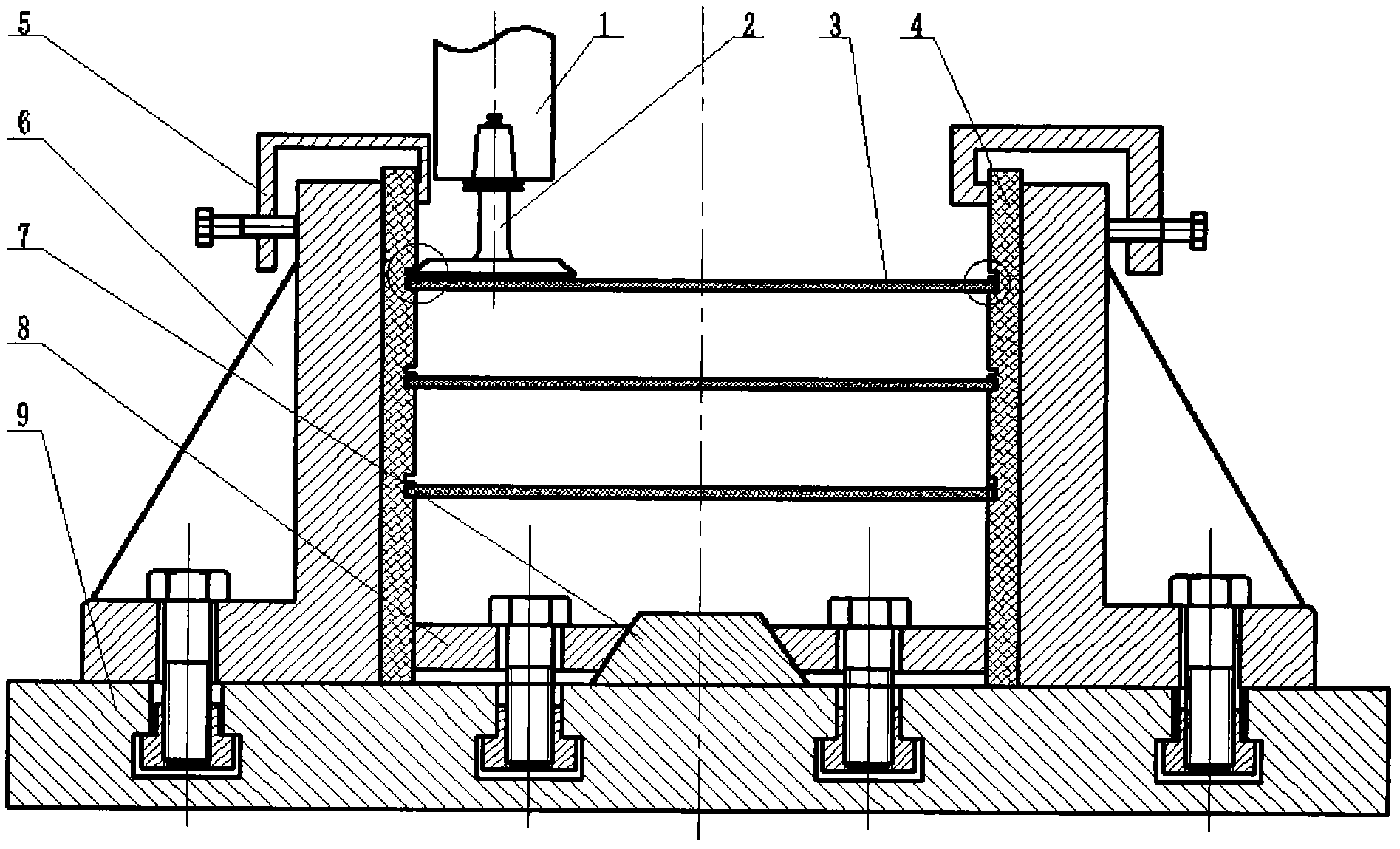
[0034] A rolling assembly mechanism, comprising: a CNC machine tool workbench 1, a symmetrically arranged clamping support body 6 is fixedly installed on the CNC machine tool workbench, the clamping support body 6 is provided with reinforcing ribs, and the inner wall of the clamping support body 6 There are workpieces 4 on the top respectively, the clamping support body 6 and the upper part of the workpiece 4 are fastened by the clamp 5, the opposite surface of the workpiece 4 is symmetrically opened with a rolling groove, and the second workpiece 3 is installed in the rolling groove, and the inner bottom of the workpiece 4 is opposite A first clamping wedge 8 and a second clamping wedge 7 are provided respectively, and the second clamping wedge 7 is placed in the middle of the first clamping wedge 8 .

[0035] The rolling assembly steps are as follows:

[0036] 1) A symmetrically arranged clamping support body 6 is fixedly installed on the workbench 1 of the CNC machine tool,...


PUM


Abstract

The invention relates to a rolling assembly mechanism and method, and belongs to the technical field of machinery manufacturing. In the mechanism, the worktable of a numerical control (NC) machine tool is fixedly equipped with symmetrical clamping support bodies; workpieces are respectively arranged on the inner walls of the clamping support bodies, and each clamping support body is fastened with the upper part of each workpiece through a clip; rolling grooves are symmetrically arranged at opposite sides of each workpiece; second workpieces are arranged in the rolling grooves at opposite inner sides of each workpiece; and a first clamping wedge block and a second clamping wedge block are respectively arranged at the bottom parts of the opposite inner sides of each workpiece, and the second clamping wedge block is placed in the middle of the first clamping wedge block. In the method, part machining and component assembly are carried out on one set of equipment, and after the cutting and machining of parts, the parts are continuously assembled in a rolling manner rather than being disassembled so as to meet the uniform standard for part machining and assembly operation; a special rolling wheel is adopted to roll at a NC machine center so as to realize the accurate control of the rolling precision; and the form and position tolerance of the finally assembled components meets the drawing requirements, and technical indexes such as bonding force, clearance and the like also meet the requirements, and the components have good consistence.

Description

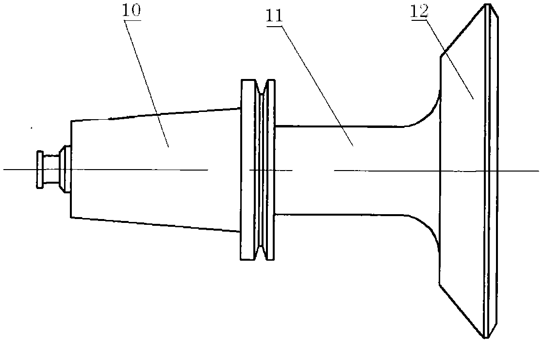
technical field [0001] The invention relates to a rolling assembly mechanism and an assembly method, belonging to the technical field of mechanical manufacturing. Background technique [0002] Some product structures are plug-in combinations of parts and parts, and have a certain bonding force through mechanical extrusion (product performance requirements). Typically, thin plate parts with convex edges and thin plate parts with grooves are inserted and extruded (usually parts made of plastic metal materials), and the geometric and dimensional tolerances of the components are strictly required. At present, the general method of its assembly process is: each component is manufactured, inserted into the assembly, and then squeezed and combined with rollers. [0003] This kind of rolling work is a special process, which is difficult to realize without suitable fixtures and unique process solutions. Thin plate parts are easily deformed in multiple clampings in different process...

Claims


Application Information

Patent Timeline
IPC IPC(8): B23P23/02B23P11/00B23Q3/06
Inventor 王美任学平李来平刘文忠贾占军
Owner INNER MONGOLIA NORTH HAULER
Learn More