Four-roller connection-rod vacuum electron beam wire feeder
A vacuum electron beam and wire feeder technology, applied in electron beam welding equipment, welding equipment, metal processing equipment, etc., can solve the problem that the wire feeding roller and the wire pressing roller are easy to wear and cannot be adjusted automatically. Clearance and other problems, to achieve the effect of smooth wire feeding, solving electromagnetic interference, and improving service life
- Summary
- Abstract
- Description
- Claims
- Application Information
AI Technical Summary
Problems solved by technology
Method used
Image
Examples
specific Embodiment approach 1
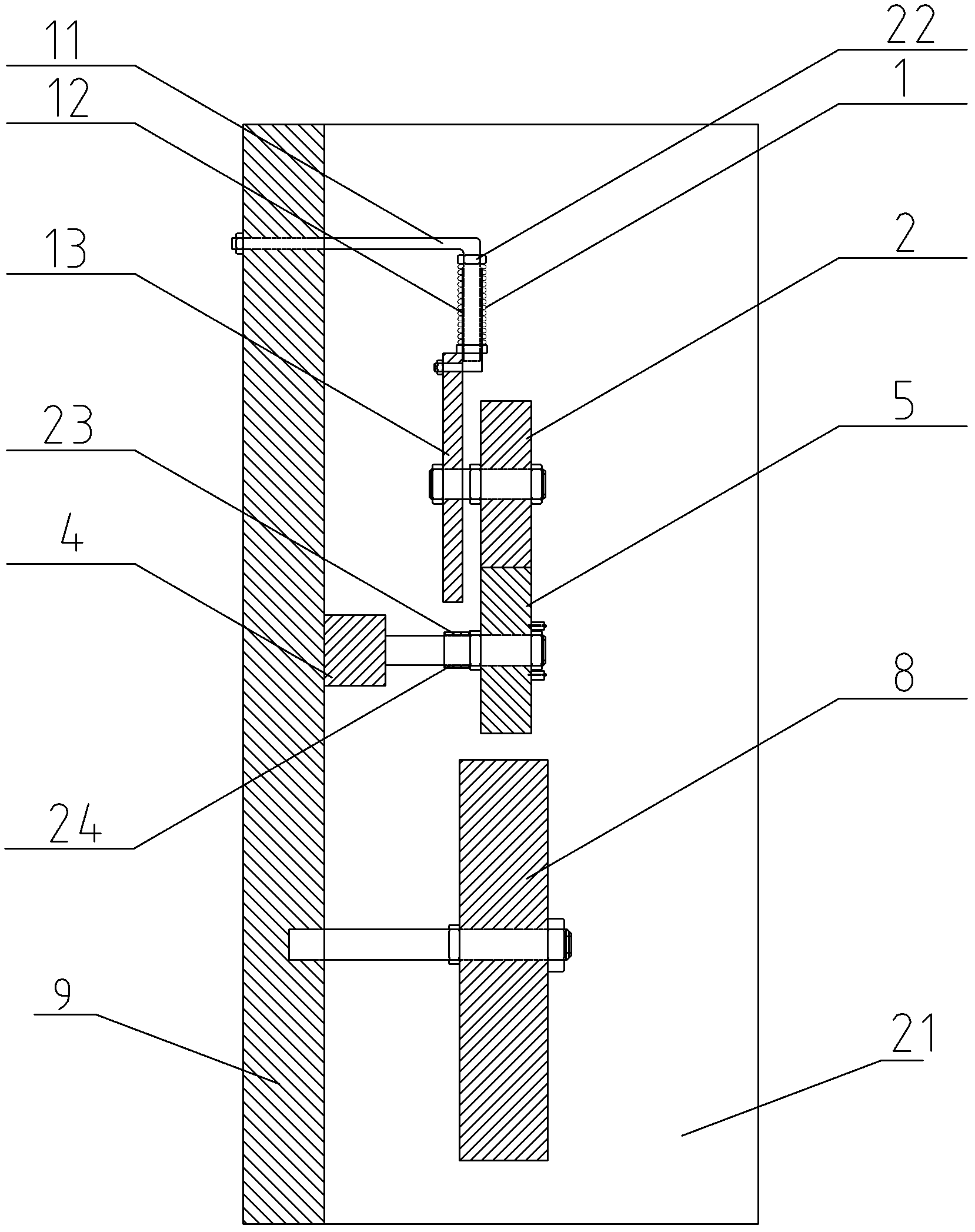
[0009] Specific implementation mode one: as Figure 1~4 As shown, the four-wheel linkage vacuum electron beam wire feeder described in this embodiment includes a vacuum chamber and a wire feeder body located therein, the metal cover 21 and the substrate 9 perpendicular to the horizontal plane form the vacuum chamber, the The main body of the wire feeder includes a servo motor 4, a bracket 13, an active wire feed roller 5, a driven wire feed roller 18, a first wire pressing roller 2, a second wire pressing roller 14, a link mechanism 20 and at least one spring limit mechanism ; The support 13 is installed on the base plate 9 by a spring limit mechanism and is arranged in parallel with the base plate 9, the servo motor 4 is fixed on the inner side wall of the base plate 9, and the active wire feeding roller 5 is installed on the output shaft of the servo motor 4. The wire feed roller 5 is connected with the driven wire feed roller 18 installed on the base plate 9 through the lin...
specific Embodiment approach 2
[0010] Specific implementation mode two: as Figure 1~4 As shown, the quantity of the spring limiting mechanism in this embodiment is two sets, and the spring limiting mechanism includes a spring 1, an L-shaped control rod 11, a sleeve 12, and the end of the horizontal side of the L-shaped control rod 11 is fixed. On the substrate 9, the vertical side of the L-shaped control rod 11 is inserted into the sleeve 12, the lower end of the sleeve 12 is fixedly connected with the upper end of the bracket 13, the spring 1 is set on the sleeve 12, and the upper end of the spring 1 is connected to the L-shaped control rod. The corresponding position of the vertical edge of 11 is connected, and the lower end of spring 1 is connected on the outer side wall of sleeve 12. The spring limit mechanism defined in this embodiment can realize the automatic adjustment between the active wire feeding roller 5 and the first wire pressing roller 2, as well as the driven wire feeding roller 18 and the...
specific Embodiment approach 3
[0011] Specific implementation mode three: as Figure 1~3 As shown, the maximum tensile force of the elastic force of the spring 1 in this embodiment should be greater than or equal to the total force of the bracket 13 and the components installed on the bracket 13 . Other components and connections are the same as those in the second embodiment.
PUM
 Abstract
Description
Claims
Application Information
 - R&D
- Intellectual Property
- Life Sciences
- Materials
- Tech Scout
- Unparalleled Data Quality
- Higher Quality Content
- 60% Fewer Hallucinations
Browse by: Latest US Patents, China's latest patents, Technical Efficacy Thesaurus, Application Domain, Technology Topic, Popular Technical Reports.
© 2025 PatSnap. All rights reserved.Legal|Privacy policy|Modern Slavery Act Transparency Statement|Sitemap|About US| Contact US: help@patsnap.com


