
Automatic laser scanning positioning steel grating numerically-controlled cutter

An automatic positioning and laser scanning technology, applied in welding equipment, gas flame welding equipment, metal processing equipment, etc., can solve the problems of inability to achieve normal cutting, low workpiece size accuracy, and inability to cut, etc., to achieve flexible and simple manual intervention, The effect of accurate size, free from manual lofting and manual cutting

Inactive Publication Date: 2012-02-22
莱州市得利安数控机械有限公司
View PDF9 Cites 23 Cited by
  • Summary
  • Abstract
  • Description
  • Claims
  • Application Information

AI Technical Summary

Problems solved by technology

[0002] (1) At present, the steel grating industry generally adopts manual lofting, manual scribing and manual hand-held flame cutting torch cutting steel grating, so the cutting quality is poor, the cutting section is rough and uneven, the workpiece size accuracy is low, and the labor intensity is high. , low cutting efficiency
[0003] (2) If the existing ordinary cutting machine is used to cut the steel grating, the following situation will occur: plasma cutting can only be used to cut thinner steel grating; Under tie condition, resulting in damage to the cutting torch, so normal cutting cannot be achieved
During flame cutting, because the flame cutting torch cannot automatically stay and preheat in the space of the steel grating, it cannot be cut.
[0004] (3) So far, there is no laser scanning automatic positioning steel grating CNC cutting machine dedicated to the automatic cutting of steel grating

Method used


Image

  • Automatic laser scanning positioning steel grating numerically-controlled cutter
  • Automatic laser scanning positioning steel grating numerically-controlled cutter
  • Automatic laser scanning positioning steel grating numerically-controlled cutter

Examples


Embodiment Construction

[0036] The present invention will be further described in detail below in conjunction with the accompanying drawings and specific embodiments.

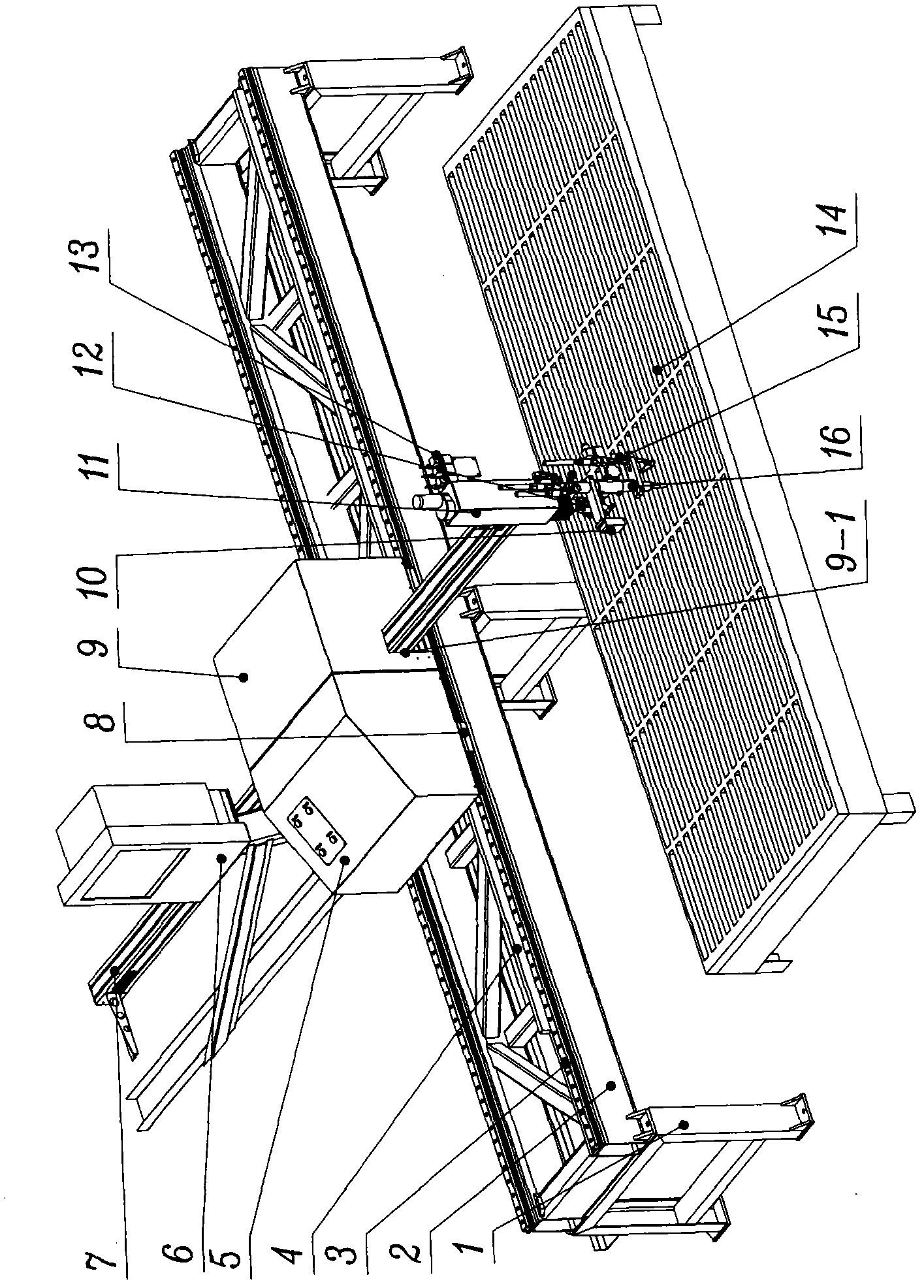
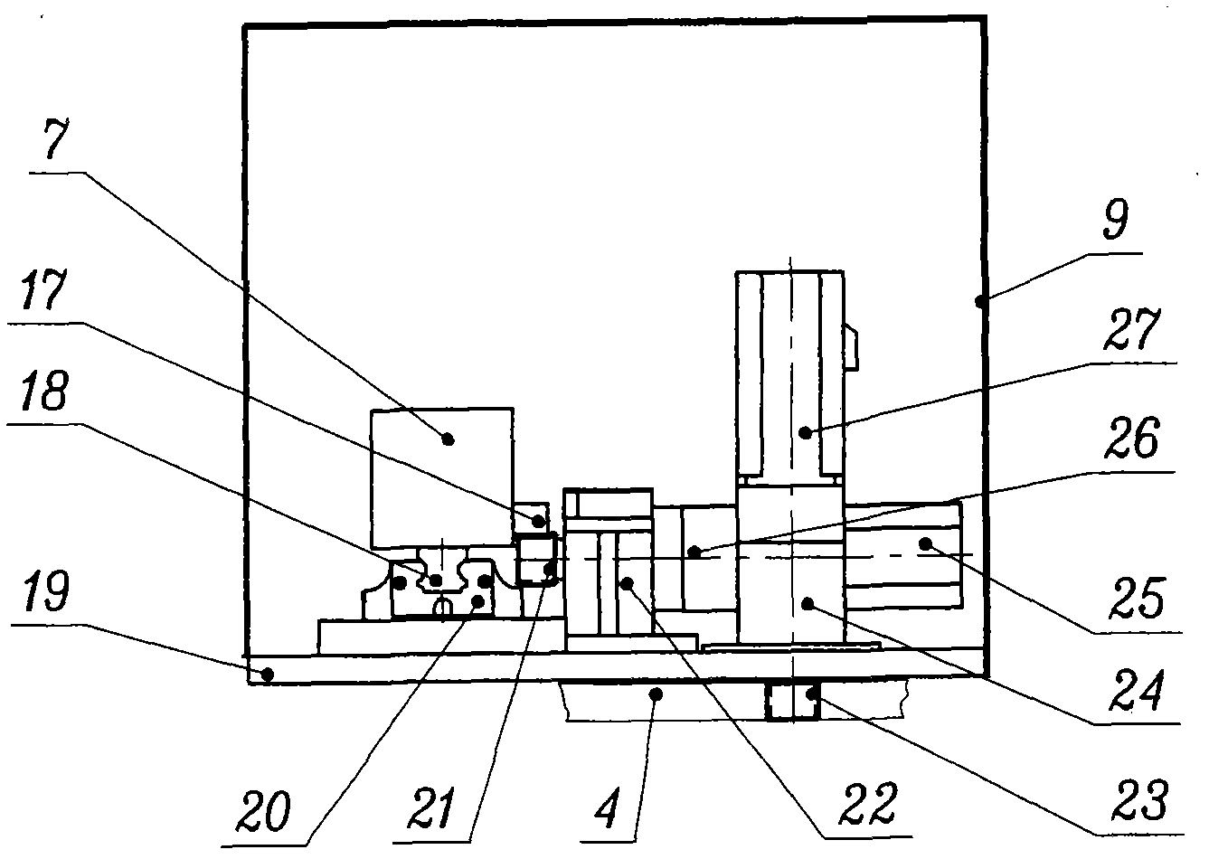
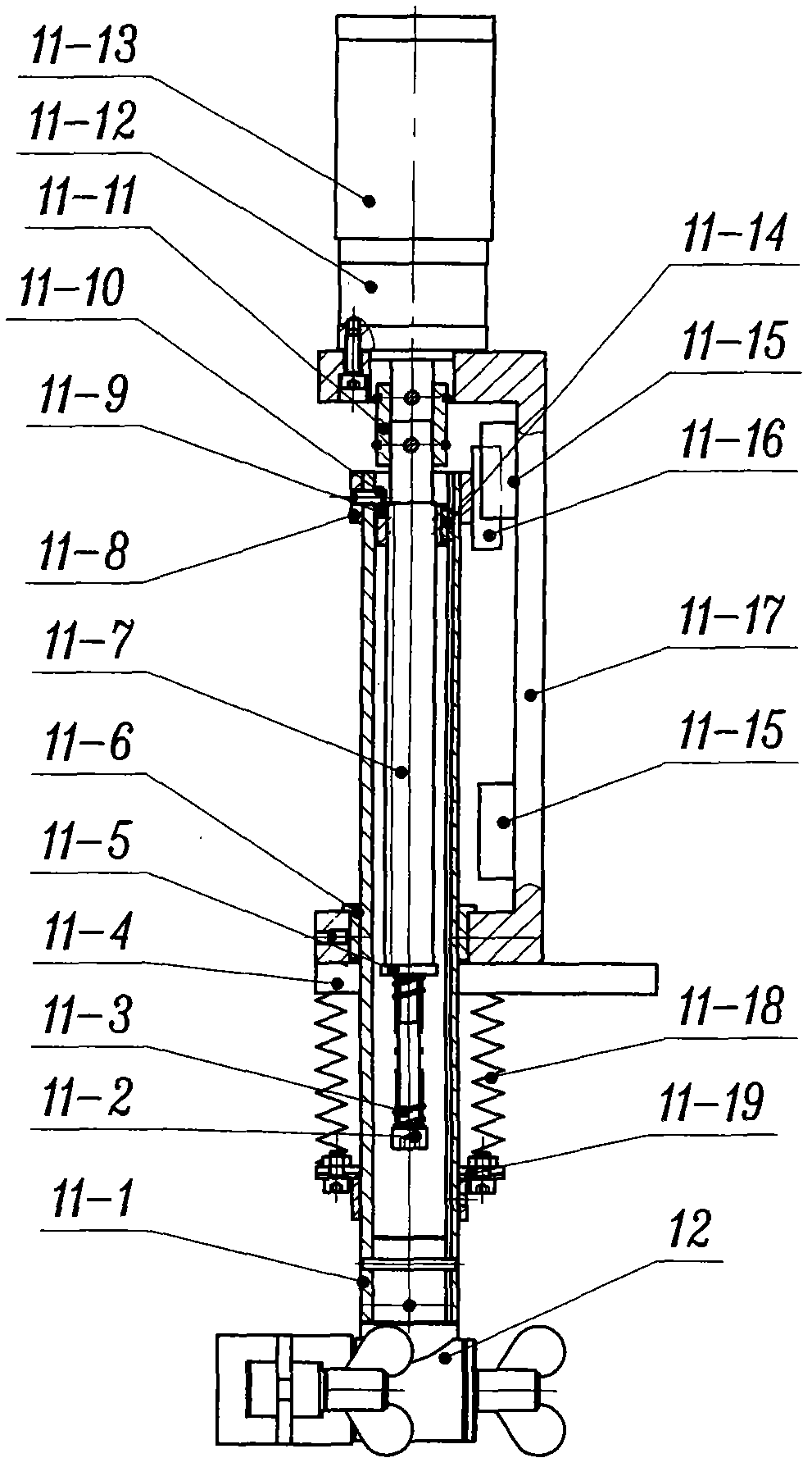
[0037] Depend on figure 1 , figure 2 , image 3It can be seen that the laser scanning automatic positioning steel grating numerical control cutting machine of the present invention includes a CNC numerical control system 6, a laser scanner 10, electrical components 5, a driving mechanism, a flame cutting torch 16 and an automatic ignition device 15; wherein:

[0038] (1) CNC numerical control system: refer to figure 1 , Figure 5 .

[0039] Such as figure 1 As shown, the CNC numerical control system 6 is a device for realizing digital control, which can perform precise calculations on scanning positions and cutting process steps. The function of CNC numerical control system is to realize the automatic control of automatic positioning, preheating, cutting and other process steps through the collection of cutting position, machin...


PUM


Abstract

The invention discloses an automatic laser scanning positioning steel grating numerically-controlled cutter, which comprises a numerical control system, a laser scanner, an electrical appliance part, a driving mechanism, a flame cutting torch and an automatic ignition device, wherein the driving mechanism comprises an X-axis driving part, a Y-axis driving part and a Z-axis automatic heightener; the Z-axis automatic heightener is arranged at one end of a beam; the laser scanner is arranged on the Z-axis automatic heightener; the bottom end of a moving lever in the Z-axis automatic heightener is provided with the flame cutting torch and the automatic ignition device by a cutting torch holder; and the transverse, longitudinal and vertical fit and linkage of the flame cutting torch can be realized under the action of the driving mechanism. The cutter can realize automatic scanning and accurate positioning and realize continuous operations to form batch production, has a high automation degree, stable and reliable performance, high production efficiency, high cutting quality and high cutting accuracy, and can be used for cutting steel gratings of any material and various specifications and shapes.

Description

technical field [0001] The invention relates to the technical field of metal cutting equipment, in particular to a laser scanning automatic positioning steel grating numerical control cutting machine. Background technique [0002] (1) At present, the steel grating industry generally adopts manual lofting, manual scribing and manual hand-held flame cutting torch cutting steel grating, so the cutting quality is poor, the cutting section is rough and uneven, the workpiece size accuracy is low, and the labor intensity is high. , the cutting efficiency is low. [0003] (2) If the existing ordinary cutting machine is used to cut the steel grating, the following situation will occur: plasma cutting can only be used to cut thinner steel grating; Under the tie-down situation, the cutting torch is damaged, so normal cutting cannot be achieved. When flame cutting, since the flame cutting torch cannot automatically stay and preheat in the space of the steel grating, it cannot be cut. ...

Claims


Application Information

Patent Timeline
IPC IPC(8): B23K7/00B23K7/10
Inventor 杨宝升杨震
Owner 莱州市得利安数控机械有限公司
Learn More