
Electrochemical machining array electrode

An array electrode and electrolyte technology, which is used in processing electrodes, electric processing equipment, electrode manufacturing, etc., can solve the problems of difficult discharge of heat and electrolysis products, high processing accuracy and processing stability, and unstable electric field and flow field. Achieve the effect of shortening production cycle, improving processing efficiency and processing quality, and uniform electric field and flow field

Inactive Publication Date: 2012-02-22
NANJING UNIV OF AERONAUTICS & ASTRONAUTICS
View PDF7 Cites 14 Cited by
  • Summary
  • Abstract
  • Description
  • Claims
  • Application Information

AI Technical Summary

Problems solved by technology

However, the main disadvantages and limitations of electrolytic machining are: (1) The complex end surface profile of the forming electrode varies with the workpiece to be processed. High requirements cause the electrode cost to account for about half of the entire processing cost; (2) It is difficult to achieve high processing accuracy and processing stability, which is caused by the instability of the electric field and flow field in the electrolytic processing gap, which is easy to cause processing Local expansion of the gap, especially difficult to process small holes or narrow seams
(3) When the area of ​​the formed electrode increases, the electrolyte in the machining gap is difficult to renew, and the heat and electrolytic products generated by electrolytic machining are difficult to discharge, resulting in low processing efficiency and poor processing quality

Method used


Image

  • Electrochemical machining array electrode
  • Electrochemical machining array electrode
  • Electrochemical machining array electrode

Examples


Embodiment 1

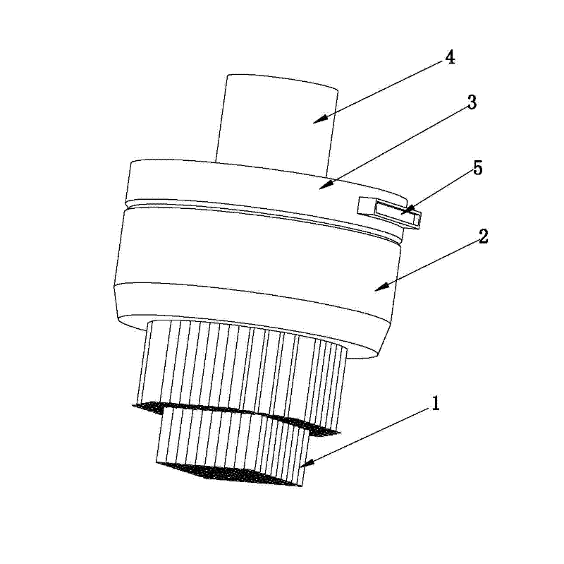
[0025] like figure 1 shown.

[0026] An electrolytic machining array electrode, which includes an electrode unit 1. When the electrode unit 1 is a strip-shaped entity, the array electrode is sequentially composed of an electrode unit 1, an electrode unit bundle clamp 2, a power module 3, and an electrode clamp joint 4. , the electrode units 1 are bundled to form an array electrode unit bundle, and the array electrode unit bundle is clamped by the electrode unit bundle clamp 2, and the bottom end of the array electrode unit bundle can form an end surface of any contour shape. The electrode units 1 can be completely conductive or completely insulated, or partially conductive to form electrode unit groups, which are insulated from each other and powered by an external power supply via the power interface 5 of the power module 3 . When the electrode units 1 are completely insulated or partially conductive and partially insulated to form a group, the electrode units 1 can be selec...

Embodiment 2

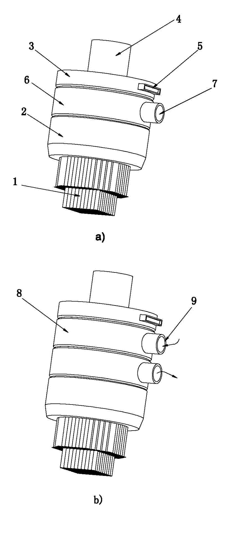
[0028] like figure 2 , 3 shown.

[0029] The difference between this embodiment and the first embodiment is that the section of the electrode unit 1 is hollow or slotted, figure 2 The electrode unit 1 is a thin-walled hollow or slotted structure. in figure 2 (a) Array electrode when adding an electrolyte module, figure 1 (b) Array electrode when adding two electrolyte modules. When the electrode unit is a thin-walled hollow structure or a slotted structure, the electrolytic machining array electrode also includes an electrolyte module 6, so that the electrode unit 1 can realize liquid flushing or liquid absorption, or add two electrolyte modules 6 and 8, respectively with different The electrode units 1 are connected, so that part of the electrode units 1 flush liquid, and part of the electrode units 1 absorb liquid. The electrolyte module is provided with electrolyte interfaces 7 and 9 .

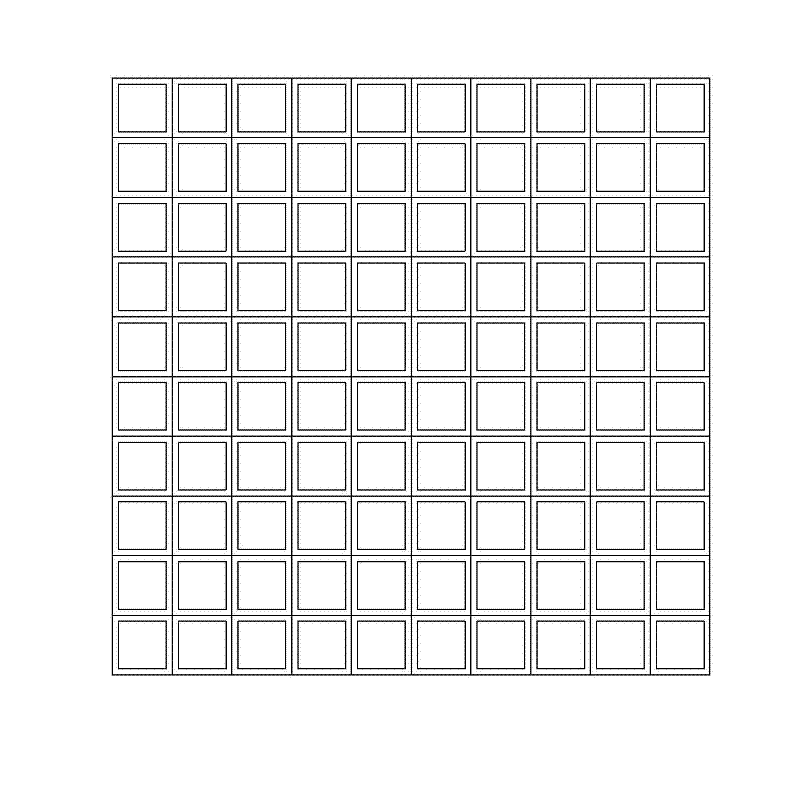
[0030] image 3 It is a schematic plan view of quadrilateral section electro...


PUM


Abstract

The invention discloses an electrochemical machining array electrode which is characterized by comprising electrode units, an array electrode clamp, a power module and an electrode clamp joint. The electrode unit is a strip-shaped solid, or a thin-wall hollow or grooved structure; the electrode units are clustered to form an array electrode unit cluster; the array electrode unit cluster is clamped by an electrode unit clamp; the bottom end of the array electrode unit cluster can form an end surface of any contour shape; and if the electrode unit is a thin-wall hollow structure or grooved structure, the electromechanical machining array electrode also comprises an electrolyte module so that the electrode units realize liquid flushing or absorption, or partial liquid flushing and partial liquid absorption. Through the invention, the electrode production time of electrolytic formation machining can be obviously shortened, the cost and difficulty in the electrode production are reduced, the utilization rate of the electrode material is improved, and the machining efficiency and speed are improved; and meanwhile, the electric field and flow field during the electromechanical machining are homogenized, selective machining can be realized at different positions of the electrode, and the machining accuracy and quality are improved.

Description

technical field [0001] The invention relates to an electrolytic machining array electrode, which belongs to the field of electrolytic machining. Background technique [0002] Electrolytic machining is the use of electrochemical anodic dissolution of metals in electrolytes to shape workpieces. Electrolytic machining has the advantages of wide processing range, good surface quality, high productivity, no loss of tool electrodes, complex cavity, surface, and hole, and is not limited by the strength of the material. At present, electrolytic machining has been widely used in aerospace, weapons, automobiles, medical equipment and other industries, and has become an indispensable process method in the machinery manufacturing industry. However, the main disadvantages and limitations of electrolytic machining are: (1) The complex end surface profile of the forming electrode varies with the workpiece to be processed. High requirements cause the electrode cost to account for about ha...

Claims


Application Information

Patent Timeline
Patent Type & Authority Applications(China)
IPC IPC(8): B23H3/04
Inventor 沈理达王桂峰高雪松邱明波刘志东田宗军黄因慧
Owner NANJING UNIV OF AERONAUTICS & ASTRONAUTICS
Learn More