Method for improving output peak power of semiconductor laser unit
What is Al technical title?
Al technical title is built by PatSnap Al team. It summarizes the technical point description of the patent document.
A peak power and laser technology, applied in the field of lasers, can solve the problems of Joule heat junction temperature rise, optical damage of crystal materials at the end face, device degradation, etc., and achieve the effect of increasing the output peak power
Inactive Publication Date: 2012-02-15
ZHEJIANG UNIV
View PDF4 Cites 0 Cited by
Summary
Abstract
Description
Claims
Application Information
AI Technical Summary
This helps you quickly interpret patents by identifying the three key elements:
Problems solved by technology
Method used
Benefits of technology
Problems solved by technology
[0005] At present, there are two main factors that hinder the high power of LD: (1) as the injection current increases, the Joule heat generated will cause the junction temperature to rise, resulting in device degradation; (2) under high power conditions, the end face lasing area High power densities lead to sudden optical damage (COD) of the crystal material at the end face
Method used
Image
Click on the blue label to locate the original text in one second.
Reading with bidirectional positioning of images and text.
Examples
Embodiment Construction
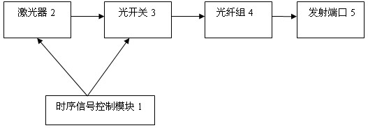
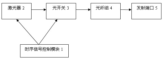
[0019] As shown in the drawings, the present invention includes a timing signal control module 1 , a laser 2 , an optical switch 3 , an optical fiber group 4 and a transmitting port 5 . The optical fiber group 4 is composed of optical fibers of different lengths. The timing signal control module 1 controls the optical switch 3 to turn on one of the optical fibers in the fiber group in turn, and at the same time close the rest of the optical fibers. The timing signal control module 1 simultaneously controls the pulse laser 2 to emit m optical pulses , these m optical pulses pass through the corresponding optical fibers in the optical fiber group 4 sequentially according to the time interval of the pulses, so that each optical pulse is superimposed at the emission port 5, thereby increasing the output peak power of the semiconductor laser, which can reach the original peak power m times.
[0020] The present invention improves the principle of semiconductor laser output power: ...
PUM
Abstract
The invention discloses a method for improving the output peak power of a semiconductor laser unit. the method is characterized in that an optical fiber group is composed of optical fibers (different in length); a time sequence signal control module controls an optical switch to sequentially open one optical fiber in the optical fiber group and simultaneously close the other optical fibers; the time sequence signal control module simultaneously controls the laser unit to emit m optical pulses, then the m optical pulses sequentially pass through corresponding optical fibers in the optical fiber group at a time interval of the pulses, so that the optical pulses are superposed at an emitting port, thereby improving the output peak power of the semiconductor laser unit. By using the method disclosed by the invention, under the condition of not increasing the peak power of the laser unit and the number of the laser unit, the output peak power of the semiconductor laser unit is improved. The method disclosed by the invention is widely used in the military field, and mainly used for guidance, fuses, night-view optical sources, laser radars, detonating, distance measurement, reconnoiter, recognition, and the like; meanwhile, besides being applied to the military field, the method is also mainly applied to the fields of medical treatment, machining, communication, optical disks, printing, displaying, computer, and the like.
Description
technical field [0001] The invention relates to a laser, in particular to a method for increasing the output peak power of a semiconductor laser. Background technique [0002] Semiconductor laser, also known as laser diode (LD), is a device that produces stimulated emission by using a certain semiconductor material as a working substance. Its working principle is that through a certain excitation method, an unbalanced load is achieved between the energy band (conduction band and valence band) of the semiconductor material, or between the energy band of the semiconductor material and the energy level of impurities (acceptor or donor). The particle population of the flow is reversed. When a large number of electrons in the particle number inversion state recombine with holes, stimulated emission will occur. There are three main excitation methods for semiconductor lasers, namely electric injection, optical pumping and high-energy electron beam excitation. Electrically inject...
Claims
Application Information
Patent Timeline
Application Date:The date an application was filed.
Publication Date:The date a patent or application was officially published.
First Publication Date:The earliest publication date of a patent with the same application number.
Issue Date:Publication date of the patent grant document.
PCT Entry Date:The Entry date of PCT National Phase.
Estimated Expiry Date:The statutory expiry date of a patent right according to the Patent Law, and it is the longest term of protection that the patent right can achieve without the termination of the patent right due to other reasons(Term extension factor has been taken into account ).
Invalid Date:Actual expiry date is based on effective date or publication date of legal transaction data of invalid patent.