
Timing invalidation control device of hypocenter bomb

A timing failure and control device technology, applied to measuring devices, seismology, instruments, etc., can solve problems affecting construction progress, hidden safety hazards, casualties, etc., and achieve the effect of obvious price advantage, safe operation, and low cost

Active Publication Date: 2012-02-15
邵水源 +1
View PDF7 Cites 0 Cited by
  • Summary
  • Abstract
  • Description
  • Claims
  • Application Information

AI Technical Summary

Problems solved by technology

[0003] The traditional method of removing dud bombs is engineering excavation, that is, after positioning the unexploded dud bombs through GPS technology, engineers dig out the dud bombs buried in the ground by digging. The main disadvantages of this method are two : First, there are potential safety hazards in the excavation process. Improper construction methods may detonate dud bombs, causing casualties; second, excavation affects the construction progress, resulting in an increase in project cost
The main disadvantages are: first, the electrical signal of the detonator Bunsen interferes with the safe detonation of the seismic source bomb, which improves the technical requirements for the detonation of the seismic source bomb; second, the production, installation, transportation and use of the detonator are very strict, which will also increase The overall cost of the source bomb; the third is that when the detonator is detonated, the dud bomb may be detonated, causing a safety accident

Method used


Image

  • Timing invalidation control device of hypocenter bomb
  • Timing invalidation control device of hypocenter bomb
  • Timing invalidation control device of hypocenter bomb

Examples


Embodiment Construction

[0026] The present invention will be further described in detail through specific embodiments below.

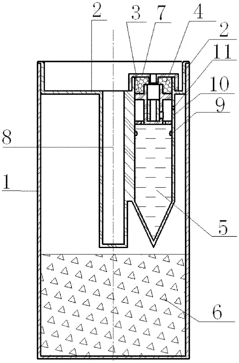
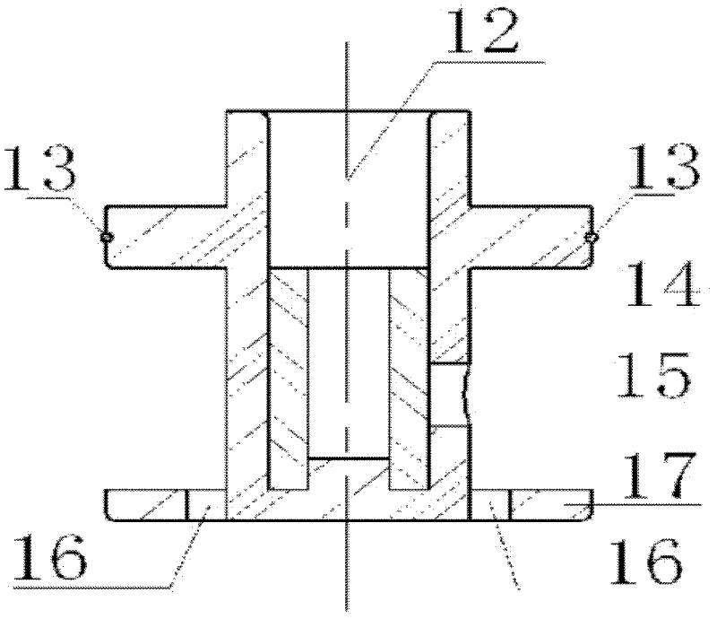
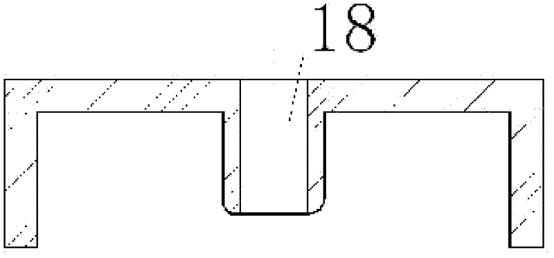
[0027] Such as figure 1 As shown, the timed failure control device is composed of 7 independent parts: the outer cylinder 1, the outer cover 2, the I-shaped piece 3, the liquid-absorbing expansion material 4, the failure control liquid 5, the explosive 6, and the cylindrical conical tube The outer cover 7; the timing failure control device of the seismic source projectile, the specific structure is, including an outer cylinder 1 and an explosive 6 arranged at the bottom of the inner cavity of the outer cylinder 1, and the upper part of the inner cavity of the outer cylinder 1 is provided with a cylindrical tube 8 for placing a detonator , wherein, the cylindrical tube 8 on the upper part of the inner cavity of the outer cylinder 1 is juxtaposed with a cylindrical tapered tube 10 with a sealed structure at the bottom; the lower part of the inner cavity of the cylindrical taper...


PUM


Abstract

The invention discloses a timing invalidation control device of a hypocenter bomb, which comprises an outer barrel and an explosive arranged at the bottom of an inner cavity of the outer barrel. The upper part of the inner cavity of the outer barrel is provided with a cylinder for placing a detonator; a cylinder conical pipe is further distributed parallel to a cylinder pipe at the upper part of the inner cavity of the outer barrel; the lower part of an inner cavity of the cylinder conical pipe is filled with an invalidation control liquid; further, the inner wall of the cylinder conical pipeis provided with a limiting ring which is arranged below the liquid level of the invalidation control liquid; an I-shaped component is arranged in the inner cavity of the cylinder conical pipe and isfurther positioned above the liquid level of the invalidation control liquid; the pipe wall of the cylinder conical pipe at the outer side of the I-shaped component is provided with a communicating hole; the upper end of the I-shaped component is in overlap joint with an outer cover of the cylinder conical pipe; a liquid-absorbing expanding material is filled between the upper end of the I-shapedcomponent and the outer cover of the cylinder conical pipe; the I-shaped component is sealed with the cylinder conical pipe through an O-shaped sealing ring; and the top wall of the outer barrel is sealed through the outer cover. By using the timing invalidation control device of the hypocenter bomb, the sealing state of a shell of the hypocenter bomb can be effectively maintained; the explosion function of the hypocenter bomb is guaranteed; and under the condition that a dud bomb appears, the invalidation time of the hypocenter bomb can be controlled in a timing way.

Description

technical field [0001] The invention relates to the failure control of seismic source bombs used in geological exploration and oilfield survey, in particular to a timed failure control device for seismic source bombs. Background technique [0002] Seismic bombs are widely used in geological exploration and oilfield surveying. Its main structure is to assemble a certain quality of high-energy explosives in a sealed container of a specific shape. Under the excitation of strong light, strong heat, or electromagnetic waves, the explosives are detonated through a detonator. Generates high energy and vibration waves. With the help of specific analysis methods, the generated energy and vibration waves are analyzed to judge the geological conditions and oilfield conditions, and provide reliable data for geological exploration and oilfield exploration. important position and role. However, due to accidental uncontrollable factors in the links of production, assembly, transportation...

Claims


Application Information

Patent Timeline
Patent Type & Authority Applications(China)
IPC IPC(8): G01V1/104
Inventor 邵水源彭龙贵王宇王启强王知
Owner 邵水源
Learn More