
Shallow water type flow rising circulation reoxygenation device

A shallow water, oxygen chamber technology, applied in water aeration, water/sludge/sewage treatment, sustainable biological treatment, etc., can solve the problems of black and odorous lake water, difficult to set up, difficult to fix, etc., to achieve oxygen diffusion Fast speed, strong reoxygenation ability, and the effect of increasing the area

Inactive Publication Date: 2012-02-15
SOUTHEAST UNIV
View PDF4 Cites 1 Cited by
  • Summary
  • Abstract
  • Description
  • Claims
  • Application Information

AI Technical Summary

Problems solved by technology

[0002] The exposure of algal blooms causes the lake water to turn black and smelly, which not only seriously deteriorates the ecology of the lake, but also seriously threatens the drinking safety of water sources. The best emergency treatment technology at present is the rapid oxygenation of black and odorous water bodies, but the traditional water body oxygenation technology is Oxygenation of large-area shallow lakes has various technical limitations. For example, microporous aeration is difficult to deploy in large-area water bodies due to inconvenient installation; surface aerators consume a lot of energy, are difficult to fix, and have high maintenance costs; patented multi-functional pumping aeration The device has problems such as sediment and low oxygenation efficiency, and is only suitable for deep water body (depth > 10m) lake bottom water lifting and local oxygenation, not suitable for shallow water lake reservoir oxygenation

Method used


Image

  • Shallow water type flow rising circulation reoxygenation device
  • Shallow water type flow rising circulation reoxygenation device

Examples


Embodiment Construction

[0013] In order to make the technical means, creative features, objectives and effects of the present invention easy to understand, the present invention will be further explained below in conjunction with specific embodiments.

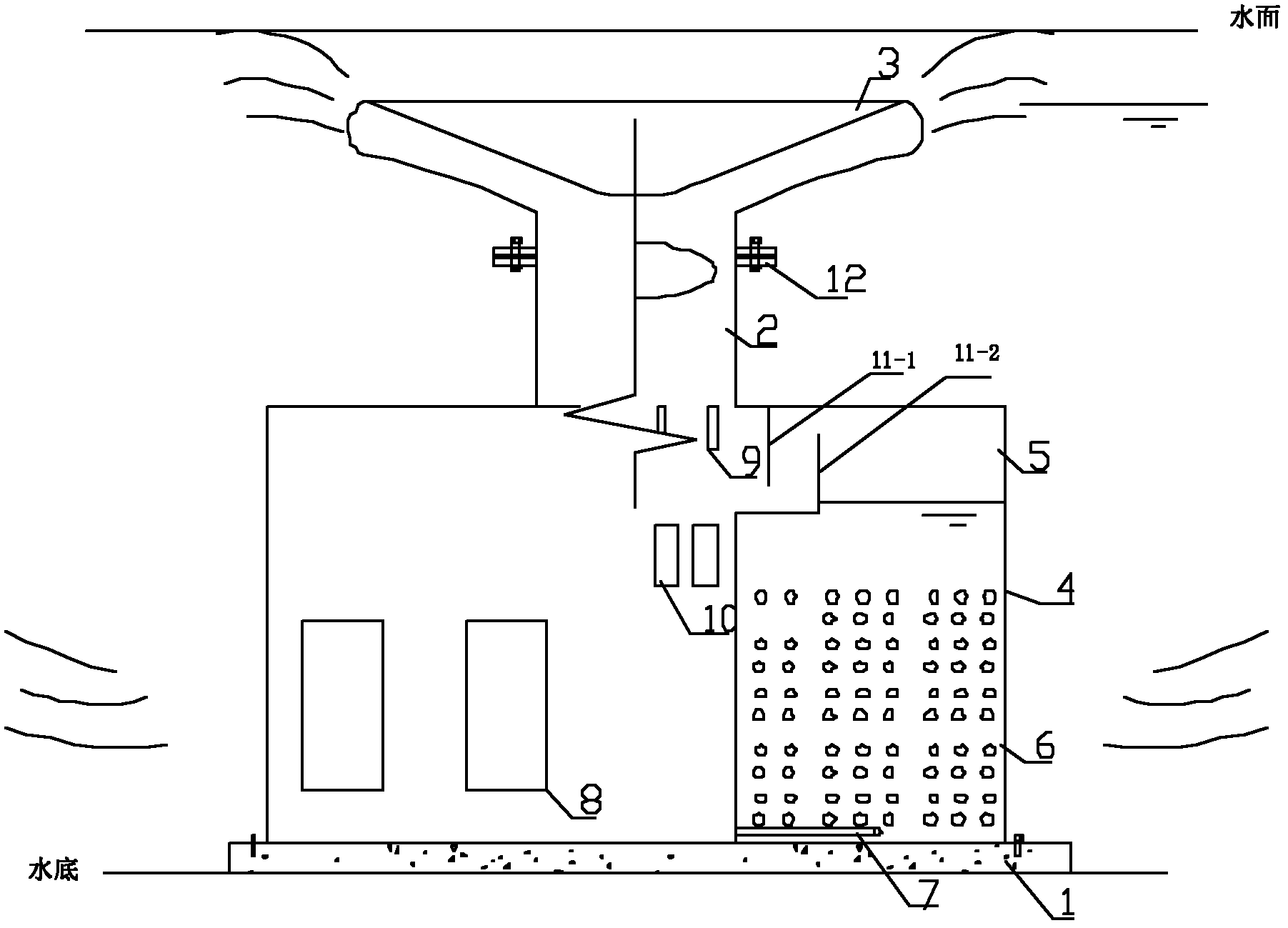
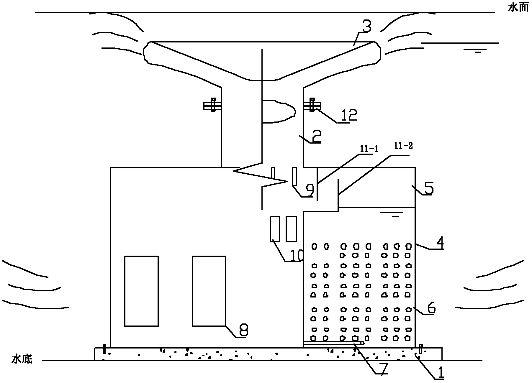
[0014] See figure 1 , The present invention includes a base 1 fixed on the underwater concrete foundation (not shown in the figure), a height-adjustable central riser 2, a release head 3 installed at the top opening of the central riser 2 through a flange 12 and fixed on The pipe 4 at the lower outside of the central rising cylinder 2.

[0015] Among them, the bottom end of the central ascending cylinder 2 is closed and fixed on the base 1; the release head 3 is in contact with the water surface; the upper and lower ends of the pipe 4 are both closed.

[0016] The area between the central ascending cylinder 2 and the pipe fitting 4 forms a collecting chamber 5 and a reoxygenation chamber 6 from top to bottom. The reoxygenation chamber 6 is provided with an ...


PUM


Abstract

The invention discloses a shallow water type flow rising circulation reoxygenation device. The device comprises a base (1) fixed at a water bottom, a central rising barrel (2) arranged on the base (1), a release head (3) which is arranged at the opening of the central rising barrel (2) and is contacted with a water surface and a pipe fitting (4) which is fixed on the outer side of the central rising barrel (2) and is provided with a sealed upper side and a sealed lower side, wherein an air collection chamber (5) and a reoxygenation chamber (6) are formed in an area between the central rising barrel (2) and the pipe fitting (4) sequentially from top to bottom; an aeration pipe is arranged in the reoxygenation chamber (6); at least one water inlet hole (8) is formed on the outer side of thereoxygenation chamber (6); and at least one air outlet hole (9) and at least one water outlet hole (10) are formed in the central rising barrel (2) at the positions of the air collection chamber (5) and the reoxygenation chamber (6). The device has low energy consumption and high reoxygenation capacity and does not stir bottom sludge; simultaneously, a water body is pushed to diffuse circularly through air oxygenation and residual air after the oxygenation, so that the area of an oxygenation service zone is substantially enlarged.

Description

Technical field [0001] The invention relates to an emergency oxygenation device, in particular to a shallow-water upflow circulating reoxygenation device, which is suitable for oxygenation of shallow-water lakes, reservoirs, ponds, and rivers (water depth≤3m). Background technique [0002] The exposure of blooms causes the lake water body to become black and smelly, which not only seriously deteriorates the lake ecology, but also seriously threatens the drinking safety of the water source. The best emergency treatment technology at present is the rapid oxygenation of the black and smelly water body, but the traditional water body oxygenation technology There are various technical limitations for the oxygenation of large-area shallow lake reservoirs. For example, microporous aeration is difficult to install in large-area water bodies due to inconvenient installation; surface aerators consume large amounts of energy, are difficult to fix, and have high maintenance costs; patented mu...

Claims


Application Information

Patent Timeline
Patent Type & Authority Applications(China)
IPC IPC(8): C02F7/00
CPCY02W10/10
Inventor 李先宁刘海洪吴磊吕锡武
Owner SOUTHEAST UNIV
Learn More