
Switchgear with rocker, especially protective switch

A switchgear and spring element technology, applied in the field of protection switches, can solve problems such as large space requirements for installation components, and achieve the effects of simplifying installation, reducing stroke loss, and contributing to structural stability

Active Publication Date: 2016-08-03
SIEMENS AG
View PDF7 Cites 0 Cited by
  • Summary
  • Abstract
  • Description
  • Claims
  • Application Information

AI Technical Summary

Problems solved by technology

[0007] The disadvantage of the prior art is the large space requirement for the mounting parts, in particular the handle and the spring, and for the area swept during the on / off movement

Method used


Image

  • Switchgear with rocker, especially protective switch
  • Switchgear with rocker, especially protective switch
  • Switchgear with rocker, especially protective switch

Examples


Embodiment Construction

[0034] figure 1 a shows a housing part 100 of a prior art switchgear, in particular a protective switch. The housing part 100 has a cylindrically formed bearing neck 101 which is designed to support the switchgear in the figure 1 A manually operable rocker 102 is shown in b. The rocker 102 basically includes a base 103 and a handle 104 formed in a cylindrical manner. In the cylindrical base body 103 , a cylindrical hollow space is formed in the center, which is provided for receiving the bearing neck 101 .

[0035] exist figure 1 Shown in c is a spring 105 known from the prior art, which can be mounted to figure 1 a on the support neck 101. exist figure 1d shows the assembly of the housing cover 106 , the rocker 102 and the spring 105 , wherein the spring 105 is here arranged on the bearing neck 101 .

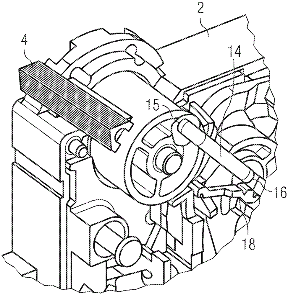
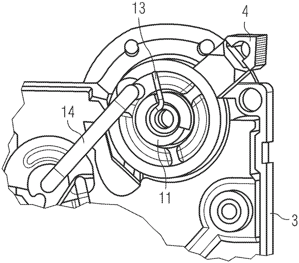
[0036] figure 2 A switching device 1 , in particular a protective switch, is shown. The switching device 1 is formed from two housing parts 2 , 3 which join together....


PUM


Abstract

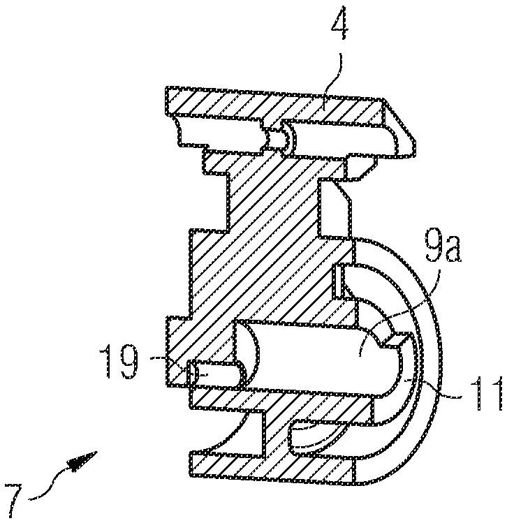
The invention relates to a switchgear (1), in particular a protective switch, the locking mechanism (18) of which can be manually operated by means of a rocker (7) supported on the housing, said rocker operating the lock The mechanism (18) can be reset to its rest position by the spring element (10). The invention is characterized in that the spring element is designed as a helical torsion spring and is mounted in the interior ( 9 a ) of the handle support neck ( 9 ).

Description

technical field [0001] The invention relates to a switchgear, in particular a protective switch, the locking mechanism of which can be manually operated by means of a rocker supported on the housing, said rocker being spring-returnable to its rest position when said locking mechanism is operated in position. Background technique [0002] The switching device is brought into its functional position by means of the actuating element or operating element, that is to say the switching device is switched on or off. Normally, a mechanical energy store, preferably a torsion spring or coil spring, is tensioned by switching on and the operating element is reset by releasing the stored spring energy when actuated by a magnetic trigger or by a thermal trigger. By adjusting the operating element, ie the switching handle, the switching adjustment is visually displayed to the operator. [0003] In a known configuration, a helical spring is used for restoring the actuating part, which he...

Claims


Application Information

Patent Timeline
Patent Type & Authority Patents(China)
IPC IPC(8): H01H23/16
CPCH01H3/06H01H71/521
Inventor W.莱特尔T.里格
Owner SIEMENS AG
Learn More