Pneumatic lifting material frame

A pneumatic lifting and material racking technology, applied in the field of lifting racks, can solve the problems of inconvenient operation, time-consuming and laborious, etc., and achieve the effect of wide application range, convenient use, and convenient maintenance

Active Publication Date: 2013-07-31
SHANGHAI XINYU ZHENCHENG ELECTRIC CONTROL TECH
View PDF1 Cites 0 Cited by
  • Summary
  • Abstract
  • Description
  • Claims
  • Application Information

AI Technical Summary

Problems solved by technology

The lifting frame is designed to meet the needs of lifting heavy objects in the factory, but this kind of manual lifting material frame is time-consuming and laborious, and the operation is inconvenient

Method used


Image

  • Pneumatic lifting material frame
  • Pneumatic lifting material frame
  • Pneumatic lifting material frame

Examples


Embodiment 1

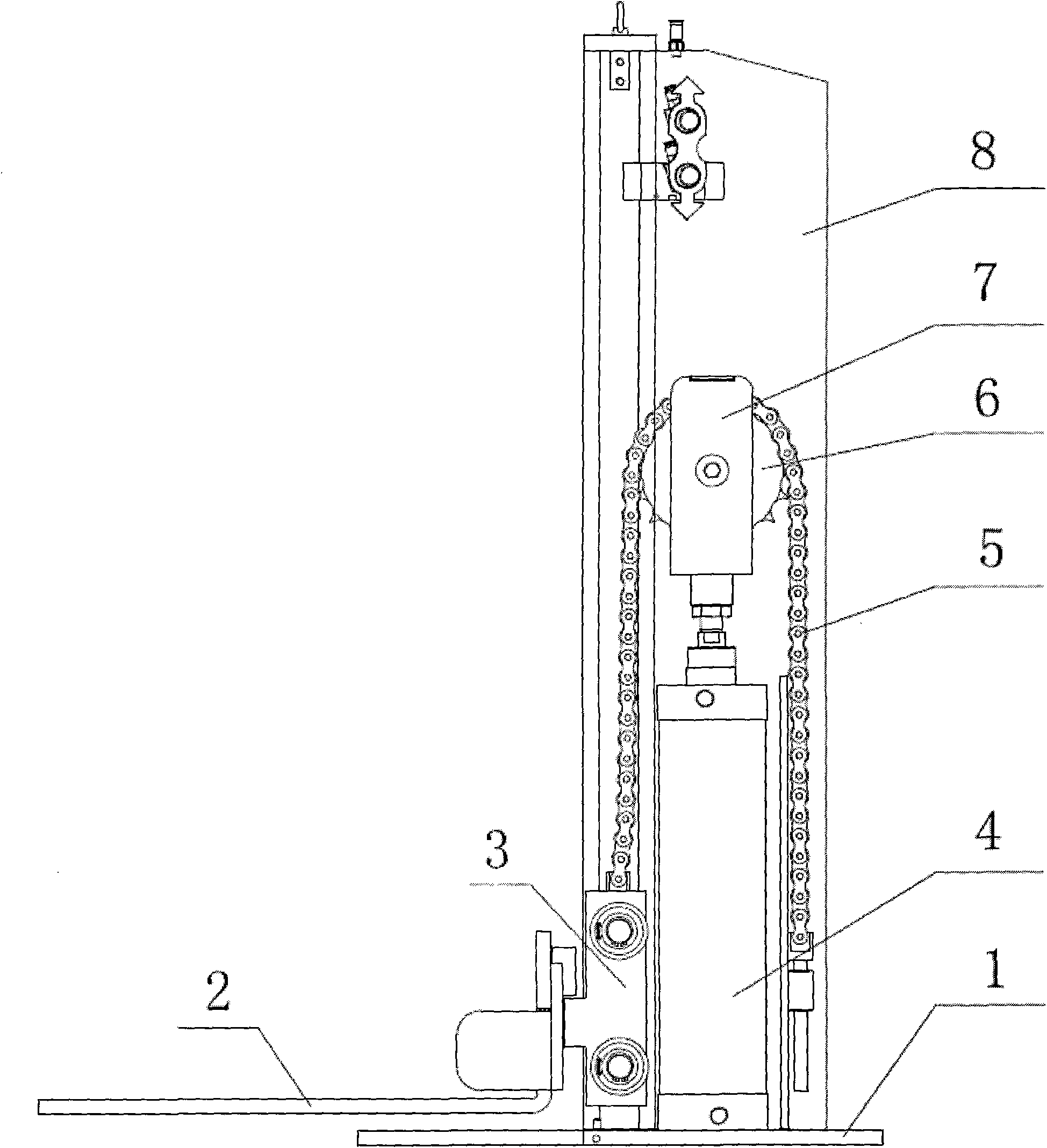
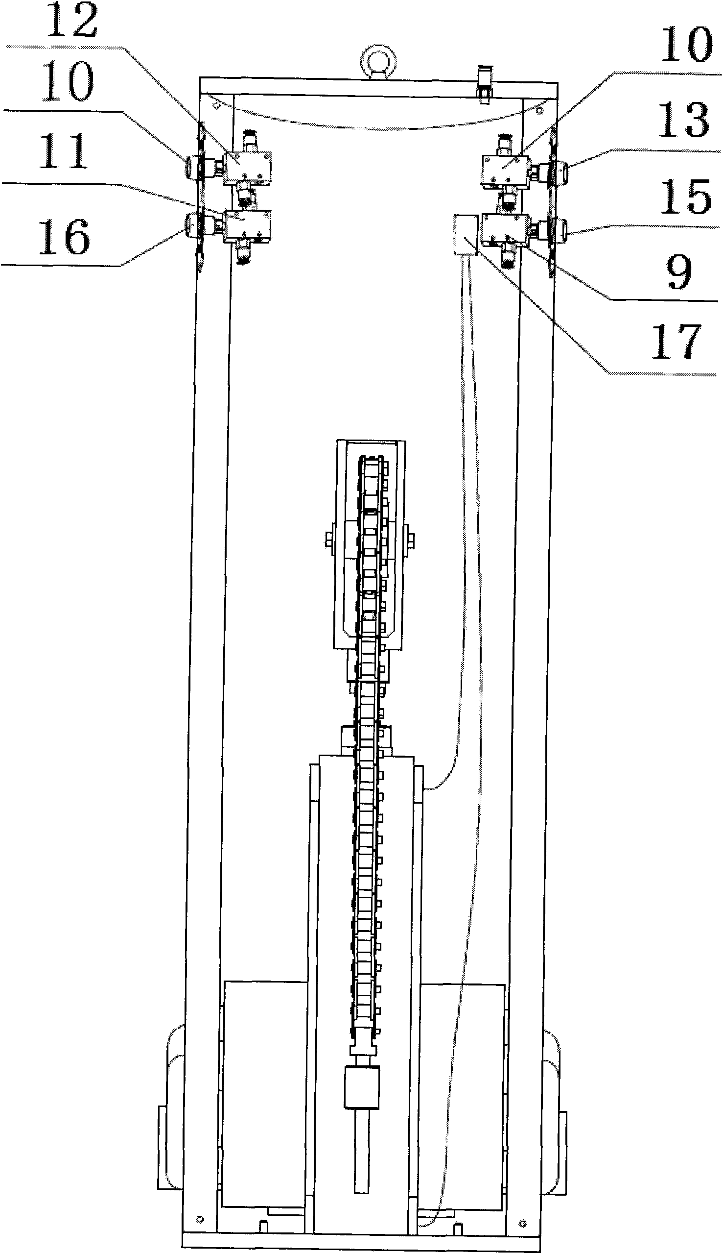
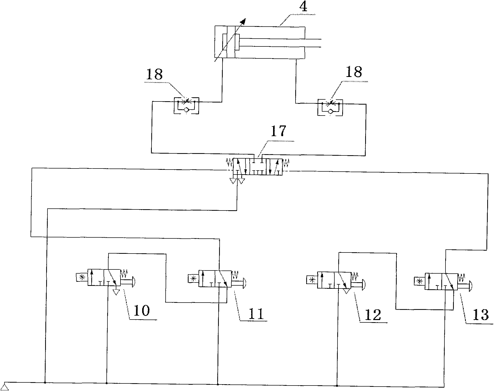
[0020] Such as Figure 1-3 As shown, a pneumatic lifting material rack includes a mechanical part and a pneumatic device, and the mechanical part includes a fixed frame 1, a lifting foot 2, a lifting foot mounting seat 3, an upper connecting frame, a sprocket 6, Sprocket mounting seat 7, chain 5, bearing, front panel and rear panel 8, the lifting foot 2 is arranged on the lifting foot mounting seat 3, which can be easily disassembled, and the lifting foot mounting seat 3 is arranged on the fixed frame 1 Above, the upper connecting frame is arranged on the fixed frame 1, and the front panel and the rear panel 8 are respectively arranged on the front and the back of the pneumatic lifting material rack; the pneumatic device includes a cylinder 4, an air control valve 17, The first switch valve 9, the second switch valve 10, the third switch valve 11, the fourth switch valve 12, the first up switch button 13, the second up switch button 14, the first down switch button 15, the sec...


PUM


Abstract

The invention relates to a pneumatic lifting material frame, which comprises a mechanical part and a pneumatic device, wherein the mechanical part comprises a fixed frame, a lifting foot, a lifting foot installation seat, an upper connection frame, a sprocket, a sprocket installation seat, a chain and a bearing, wherein the lifting foot is arranged on the lifting foot installation seat, the lifting foot installation seat is arranged on the fixed frame, and the upper connection frame is arranged on the fixed frame; and the pneumatic device comprises a cylinder, a pneumatic control valve, a switch valve, a gas-type fitting and a gas tube, wherein the cylinder is installed on a bottom plate of the fixed frame, the sprocket installation seat is arranged on the cylinder, the sprocket is arranged on the sprocket installation seat, the chain is arranged on the sprocket, one end of the chain is fixedly arranged on the fixed frame, the other end of the chain is connected with the lifting foot installation seat through the bearing, and the pneumatic control valve and the switch valve are arranged on the upper connection frame. Compared with the prior art, the invention has the advantages ofwide application range, labor conservation, environmental protection, simplicity and convenience in operation and the like.

Description

technical field [0001] The invention relates to a lifting frame, in particular to a pneumatic lifting material frame. Background technique [0002] At present, only manual, electric and hydraulic lifting racks are used to lift materials in the market, and there is no pneumatic lifting rack. Manually lifting the material rack is time-consuming and laborious, and the operation is inconvenient; the electric lifting material rack is relatively not energy-saving and not environmentally friendly; the hydraulic lifting material rack is relatively large in size and heavy, and has certain requirements on the ground quality, and it must be moved and transported. Not convenient enough. [0003] Such as Chinese patent ZL03218244.9 discloses a lifting frame, which includes an outer tube and an inner tube. An inner tube is set inside the outer tube with the outer tray, the lower end of the inner tube touches the ground, and a nut is fixed on the upper end, the nut engages with a threade...

Claims


Application Information

Patent Timeline
Patent Type & Authority Patents(China)
IPC IPC(8): B66F7/04B66F7/28
Inventor 仲峰
Owner SHANGHAI XINYU ZHENCHENG ELECTRIC CONTROL TECH
Why Eureka
Try Eureka