Method and device for positioning fuel rods in fuel assembly or fuel rod storage container
A fuel assembly and storage container technology, applied in nuclear power generation, climate sustainability, moderator/core structure, etc., can solve problems such as dense arrangement, difficulty in precise positioning of fuel rods, and small fuel rods
- Summary
- Abstract
- Description
- Claims
- Application Information
AI Technical Summary
Problems solved by technology
Method used
Image
Examples
Embodiment 1
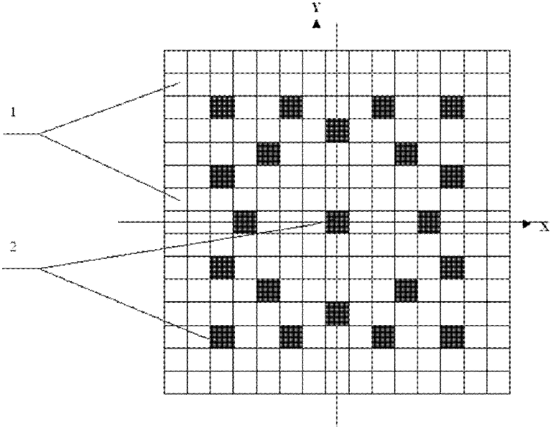
[0070] Such as figure 1 As shown, the fuel assembly of a certain power plant is closely arranged 15×15 symmetrically distributed cells, a total of 225 cells, all of which are square, and the side length of the cells is approximately equal to (slightly larger than) the cross-sectional diameter of the fuel rod.
[0071] 204 fuel rods are placed in 204 fuel rod cells 1, and 21 conduits are placed in the remaining 21 conduit cells 2. The 204 fuel rod cell-1 positions meet the requirements of every 90° rotation around the center of symmetry, and the 204 fuel rod cell-1 positions coincide with the previous ones.
[0072] The fuel rod cell-1 of 204 fuel assemblies is positioned using the method and device of the present invention, specifically as follows:
[0073] (1) Install a positioning plate above the fuel assembly or fuel rod storage container. The length and width of the positioning plate are equal to the total length and width of the symmetrically distributed cells of 15×15....
Embodiment 2
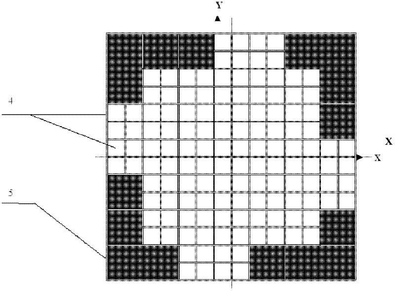
[0087] Such as image 3 As shown, the fuel rod storage container of a certain power plant is closely arranged 14×14 symmetrically distributed cells, a total of 196 cells, all of which are square, and the side length of the cell is approximately equal to (slightly larger than) the cross-sectional diameter of the fuel rod.
[0088] The 132 fuel rods are placed in the 132 fuel rod cell 2 4, and the remaining cells are blank areas 5. The positions of the 132 fuel rod cell 2 4 satisfy every rotation 90° around the center of symmetry, and the 132 fuel rod cell 2 4 Same position as before.
[0089] The fuel rod cell 2 4 of the 132 fuel rod storage containers is positioned using the method and device of the present invention, as follows:
[0090] (1) Install a positioning plate above the fuel assembly or fuel rod storage container. The length and width of the positioning plate are equal to the total length and width of the 14×14 symmetrically distributed cells. There are 33 position...
Embodiment 3
[0104] Such as figure 1 As shown, the fuel assembly of a certain power plant is closely arranged 15×15 symmetrically distributed cells, a total of 225 cells, all of which are square, and the side length of the cells is approximately equal to (slightly larger than) the cross-sectional diameter of the fuel rod.
[0105] 204 fuel rods are placed in 204 fuel rod cells 1, and 21 conduits are placed in the remaining 21 conduit cells 2. The 204 fuel rod cell-1 positions meet the requirements of every 90° rotation around the center of symmetry, and the 204 fuel rod cell-1 positions coincide with the previous ones.
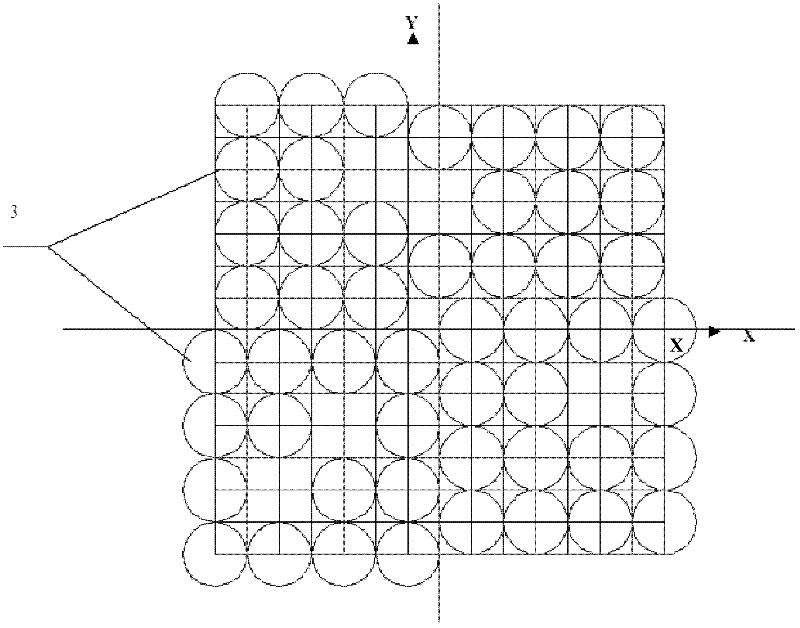
[0106] Such as figure 2 As shown, the positioning device of the present invention is a positioning plate installed above the fuel assembly or fuel rod storage container. There are 51 positioning circular holes-3 on the board, the diameter of each positioning circular hole-3 is 2.5 times the cross-sectional diameter of the fuel rod, and the center-to-center distance of a...
PUM
 Abstract
Description
Claims
Application Information
 - R&D
- Intellectual Property
- Life Sciences
- Materials
- Tech Scout
- Unparalleled Data Quality
- Higher Quality Content
- 60% Fewer Hallucinations
Browse by: Latest US Patents, China's latest patents, Technical Efficacy Thesaurus, Application Domain, Technology Topic, Popular Technical Reports.
© 2025 PatSnap. All rights reserved.Legal|Privacy policy|Modern Slavery Act Transparency Statement|Sitemap|About US| Contact US: help@patsnap.com


