
Detachable ventilated photovoltaic curtain wall

A ventilated, photovoltaic technology, applied in the direction of photovoltaic modules, photovoltaic power generation, photovoltaic module support structures, etc., can solve the problem of increased self-explosion rate of hollow photovoltaic panels, reduced power generation efficiency of battery packs, and unfavorable disassembly, replacement and maintenance of photovoltaic panels To achieve the effect of ensuring power generation efficiency, facilitating replacement and maintenance, and ensuring product quality

Inactive Publication Date: 2012-02-01
沈阳金都铝业装饰工程有限公司
View PDF9 Cites 20 Cited by
  • Summary
  • Abstract
  • Description
  • Claims
  • Application Information

AI Technical Summary

Problems solved by technology

[0007] 2. Add a layer of glass synthetic hollow plate to the photovoltaic cell plate and assemble it into the ordinary curtain wall structure. Although the thermal insulation and energy saving index (heat transfer coefficient K value) meets the national mandatory standards, it ignores the photovoltaic plate in summer. A certain amount of self-heating is generated, and the temperature of the air in the hollow layer will increase, resulting in a decrease in the power generation efficiency of the battery pack, and an increase in the self-explosion rate of the hollow photovoltaic panel.
At the same time, this structure of photovoltaic curtain wall is not conducive to the disassembly, replacement and maintenance of photovoltaic panels.

Method used


Image

  • Detachable ventilated photovoltaic curtain wall
  • Detachable ventilated photovoltaic curtain wall
  • Detachable ventilated photovoltaic curtain wall

Examples


Embodiment Construction

[0030] Below in conjunction with embodiment and accompanying drawing, concrete technical scheme of the present invention will be further described:

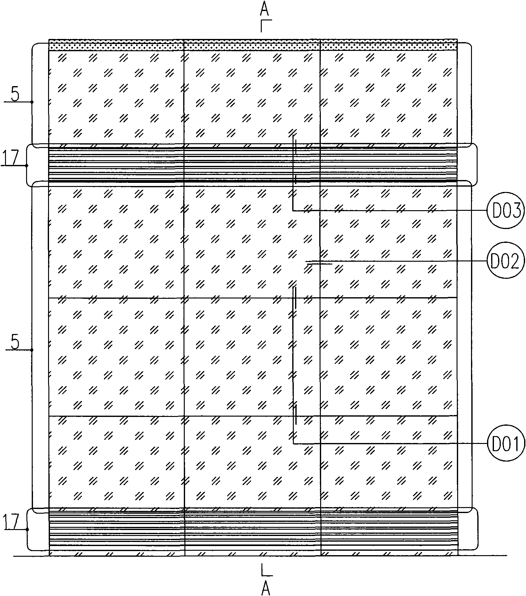
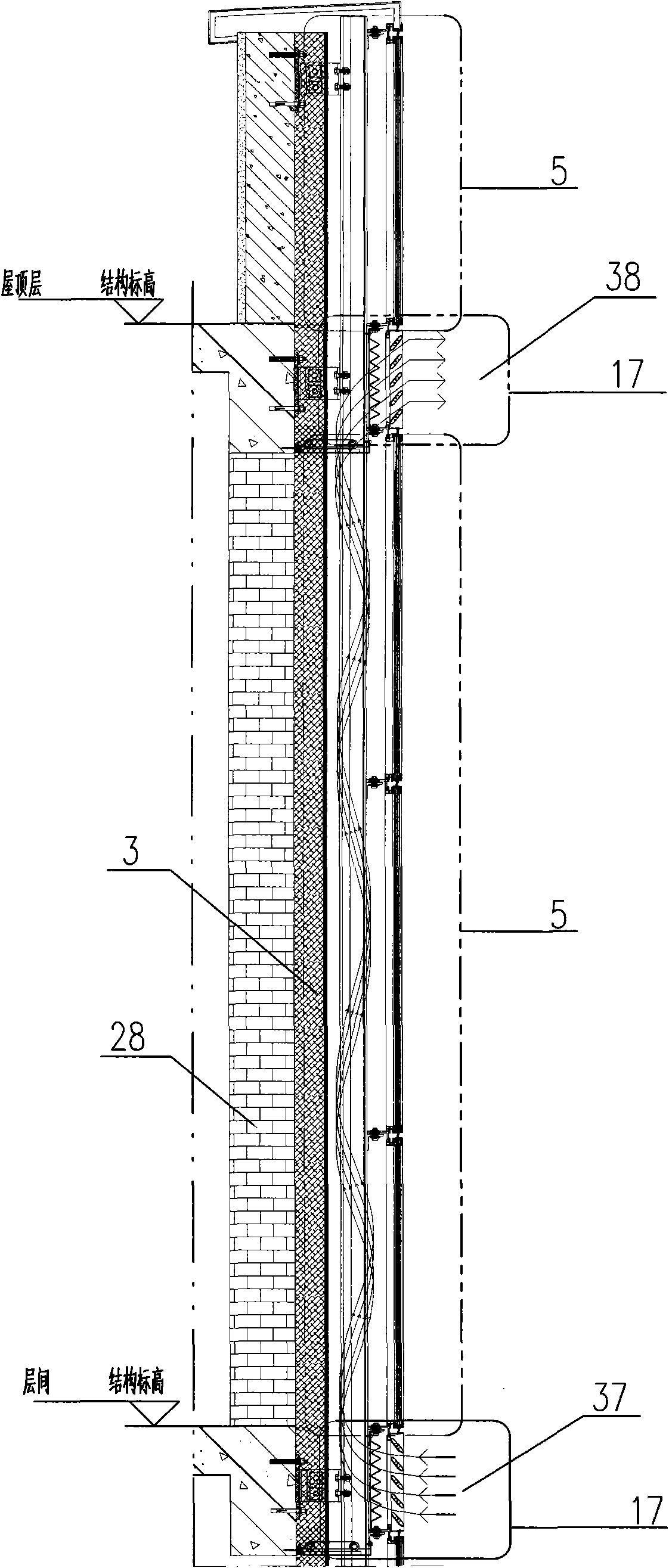
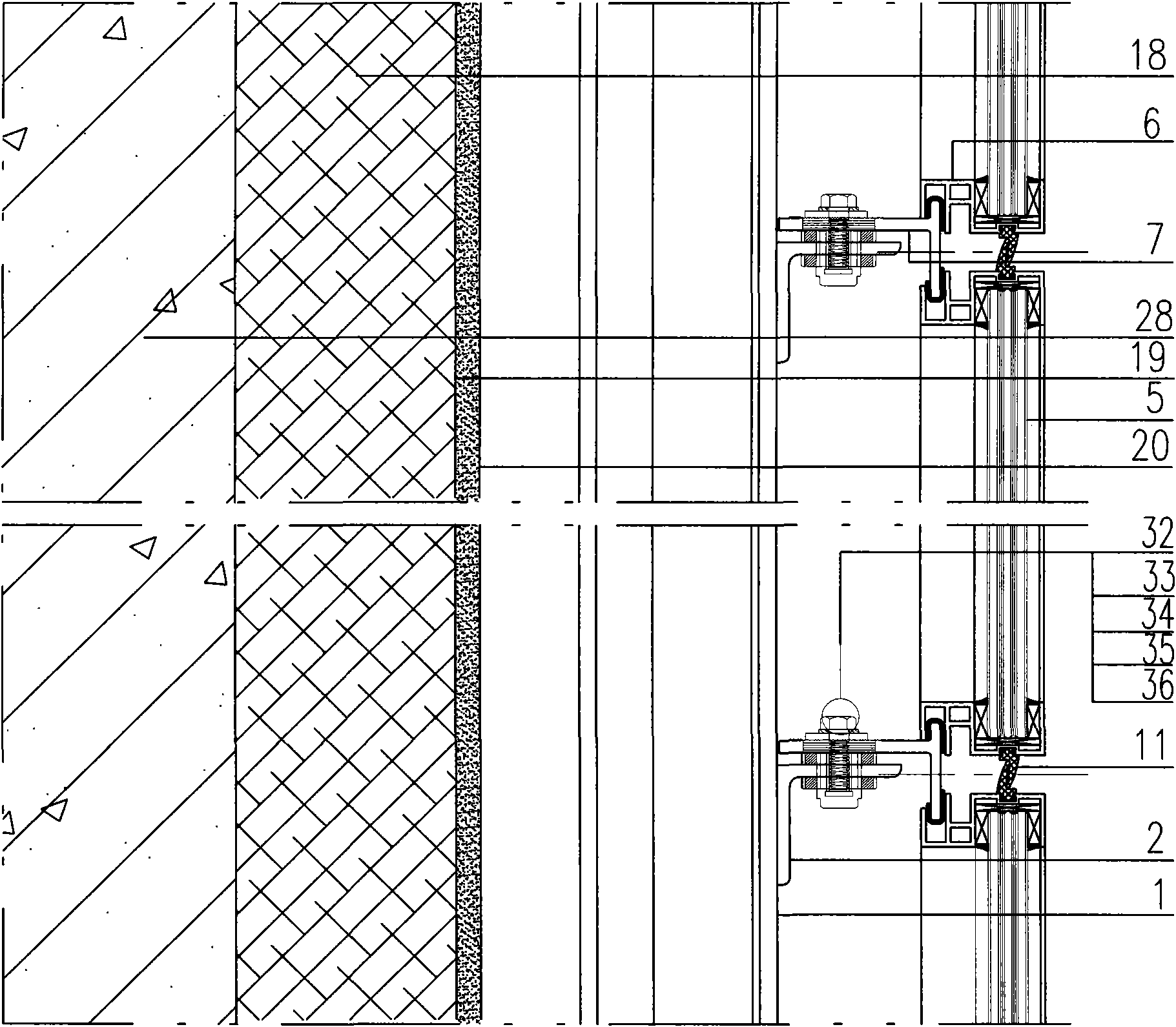
[0031] like Figure 1 to Figure 6 As shown, the partial design diagram of the solar photovoltaic curtain wall and its node diagram include a photovoltaic curtain wall body and a photovoltaic matrix control module. The structure includes columns 1, beams 2, embedded panel connectors and adjusting bolts 4. The above three parts constitute the main load-bearing structure of the photovoltaic curtain wall, and the design must meet the specifications of the curtain wall. The outer wall insulation layer 3 includes insulation material 18, steel mesh 19 and cement layer 20, and the material, density and thickness of the insulation material are selected according to architectural design requirements. A space is left between the outer wall insulation layer 3 and the panels to form a structural air duct, and the panels include ventilation l...


PUM


Abstract

The invention relates to a detachable ventilated photovoltaic curtain wall, which comprises a photovoltaic curtain wall body and a photovoltaic matrix control module, wherein the photovoltaic curtain wall body comprises a framework supporting structure, a wall body outer thermal insulation layer and plate blocks; the framework supporting structure comprises a vertical pile, beams, a buried plate, connecting pieces and adjustable bolts; the detachable ventilated photovoltaic curtain wall is characterized in that: the plate blocks comprise ventilated blade plate blocks and photovoltaic plate blocks; the photovoltaic plate blocks comprises a plate block auxiliary frame, a sandwiched glue photovoltaic cell module and a photovoltaic wiring port; the photovoltaic wiring port is connected with a signal transmission port of a photovoltaic controller; a structural air channel which is formed by spaces and in which air flows conveniently is formed between the wall body thermal insulation layer and the plate blocks; and an air outlet and an air inlet are respectively arranged on the upper part and the lower part of the structural air channel. By the invention, the problems of self-heating during power generation of the photovoltaic plate blocks and inconvenience for disassembly, replacement and repair of the photovoltaic plate blocks in the conventional photovoltaic curtain wall are solved, energy is saved, the self-heating of the plate blocks can be eliminated, and the photovoltaic plate blocks are convenient to disassemble, repair and replace.

Description

technical field [0001] The present invention relates to a photovoltaic curtain wall, in particular to a new type of photovoltaic component in BIPV (Building Integrated Photovoltaic)—a detachable ventilated photovoltaic curtain wall, which is an improvement to the existing photovoltaic curtain wall structure and belongs to solar energy Photovoltaic power generation and building solar energy integration technology field. Background technique [0002] Photovoltaic curtain wall combines photovoltaic power generation technology and curtain wall technology. It uses special resin to paste solar cells on the glass, and inlays them between two pieces of glass to convert light energy into electrical energy through batteries. It is a high-tech product. Photovoltaic curtain walls not only have energy-saving functions such as flame retardancy, heat insulation and noise reduction, but also reduce light pollution compared with ordinary glass curtain walls, representing the latest developme...

Claims


Application Information

Patent Timeline
Patent Type & Authority Applications(China)
IPC IPC(8): E04B2/88H01L31/048H02N6/00H02S20/22H02S20/26
CPCY02E10/50Y02B10/10
Inventor 朱利达鲁大伟宋金荣杨志国谢德成井欣
Owner 沈阳金都铝业装饰工程有限公司
Learn More