Boosting driving device for spindle of bending pipe arm

A driving device and spindle technology, applied in the field of driving devices, can solve the problems of reducing pipe bending accuracy, power consumption, and enlarging power equipment, etc., to achieve the effects of improving transmission efficiency, solving axial offset, and ensuring smooth transmission

Inactive Publication Date: 2012-02-01
和和机械(张家港)有限公司
View PDF7 Cites 5 Cited by
  • Summary
  • Abstract
  • Description
  • Claims
  • Application Information

AI Technical Summary

Problems solved by technology

Because the pipe bending arm needs a lot of power to start, but the existing power is not enough to make it bend under good conditions, and the space in the head of the pipe bending machine is very limited, so it is impossible to increase the power equipment, so this The structural pipe bender can only be limited to bending pipes with small diameters; in addition, when the rack is moving, there will be axial deviation due to the force, which not only consumes too much precious power, but also Reduced pipe bending accuracy

Method used


Image

  • Boosting driving device for spindle of bending pipe arm
  • Boosting driving device for spindle of bending pipe arm
  • Boosting driving device for spindle of bending pipe arm

Examples


Embodiment Construction

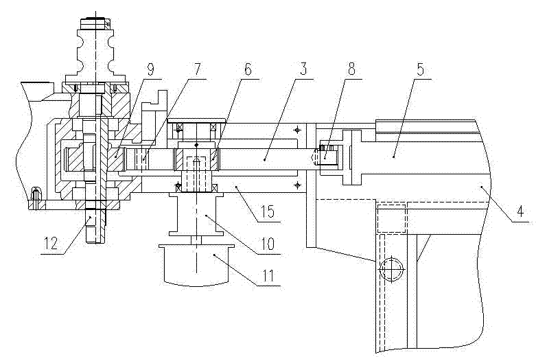
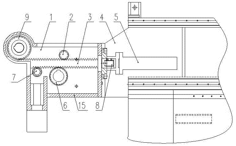
[0010] The power booster drive device for the main shaft of the pipe bending arm according to the present invention will be further described in detail below in conjunction with the accompanying drawings.

[0011] Such as figure 1 , figure 2 As shown, the booster drive device for the main shaft of the elbow arm includes: a main gear 9 fixedly installed on the main shaft 12, the rack 3 meshes with the main gear 9, and the driving gear 6 communicates with the servo motor 11 through the reducer 10 connected, the driving gear 6 is also meshed with the rack 3; like the commonly used pipe bending machine, the driving gear 6 and the rack 3 are all arranged in the inner cavity 1 of the machine head, and the reducer 10 and the servo motor 11 Installed on the housing 15 of the machine head. A one-way oil cylinder 5 is also arranged at the tail end of the rack 3, the piston rod of the one-way oil cylinder 5 is connected with the tail end 8 of the rack 3, and the one-way oil cylinder 5...


PUM


Abstract

The invention discloses a boosting driving device for a spindle of a bending pipe arm. The boosting driving device comprises a main gear which is fixedly mounted on the spindle, wherein a rack is meshed with the main gear; a driving gear is connected to a servo motor through a speed reducer; the driving gear is also meshed with the rack; a one-way cylinder is arranged at the tail end of the rack; and a piston rod of the one-way cylinder is connected to the tail end of the rack. The boosting driving device has the beneficial effects that the one-way cylinder is arranged at the tail end of the rack and the rack is simultaneously influenced by the acting forces of the servo motor and the one-way cylinder at the beginning of a bending process, thereby greatly increasing the power at the beginning of the bending process of the bending pipe arm and solving the problem that such a bending pipe machine can be used for only bending a small-bore pipe; the power transferring efficiency is promoted; the bending precision can be promoted; and the boosting driving device can be applied to a rotating bending pipe machine.

Description

technical field [0001] The invention relates to a drive device for a main shaft of a pipe bending arm in a rotary pipe bending machine. Background technique [0002] At present, a commonly used driving method for the main shaft of the pipe bending arm in the rotary pipe bending machine is: a main gear is fixedly installed on the main shaft, the rack and the main gear mesh with each other, the driving gear is connected with the servo motor through a reducer, and the driving gear Also meshes with the rack. The above-mentioned driving gears and racks are all arranged in the head of the pipe bender, and the reducer and the servo motor are installed on the housing of the head. When working, the servo motor drives the drive gear to rotate through the reducer, the drive gear drives the rack to move, and the rack drives the main gear and the main shaft to rotate, so as to achieve the purpose of pipe bending. Since the pipe bending arm needs a lot of power to start, and the existin...

Claims


Application Information

Patent Timeline
Patent Type & Authority Applications(China)
IPC IPC(8): B21D7/024
Inventor 徐乾保
Owner 和和机械(张家港)有限公司
Why Eureka
Try Eureka