Improved connection structure between disk brake mounting board and wheel hub motor shaft

A hub motor and connection structure technology, which is applied in the direction of power devices, braking components, transportation and packaging, etc., can solve the problems of low installation accuracy, decreased disc brake braking effect, and increased cumulative error, so as to achieve stable braking performance and easy installation. Convenience, good fixation effect

Inactive Publication Date: 2013-06-05
CHANGXING HUAYI ELECTROMECHANICAL
View PDF6 Cites 0 Cited by
  • Summary
  • Abstract
  • Description
  • Claims
  • Application Information

AI Technical Summary

Problems solved by technology

Although the effect of disc brakes is good, the structure is complex and the installation requirements are relatively high. Disc brakes rely on the tension of the brake line to make the brake pads in the caliper rub against and clamp the disc to produce a braking effect. Therefore, the difference between the disc and the brake pads of the disc brake The distance between the disc brake assembly and the shaft requires a good enough parallelism, and the disc and the disc brake assembly are installed on the hub and its shaft, that is to say, the installation structure between the disc brake assembly and the shaft directly affects the braking effect of the disc brake.
When installing the existing disc brakes, first install the disc brake mounting plate on the rotating shaft, and then place gaskets between the mounting plate and the hub shell until the braking surface of the disc is in the middle of the two brake pads. The plate and the mounting plate are in a relatively parallel state, and the nuts are used to lock the mounting plate to prevent the axial deviation of the mounting plate. There is a manufacturing error on each end face, and the stacking of multiple gaskets will increase the cumulative error. The installation accuracy is low, and it cannot be guaranteed that the braking surface of the disc is in the middle of the two brake pads; not only that, the gasket is easily affected by external factors. Deformation makes the installation structure unstable and the installation board is easy to move
The occurrence of above-mentioned situation just makes the braking effect of disc brake drop greatly, has brought potential safety hazard to the cyclist.

Method used


Image

  • Improved connection structure between disk brake mounting board and wheel hub motor shaft
  • Improved connection structure between disk brake mounting board and wheel hub motor shaft
  • Improved connection structure between disk brake mounting board and wheel hub motor shaft

Examples


Embodiment Construction

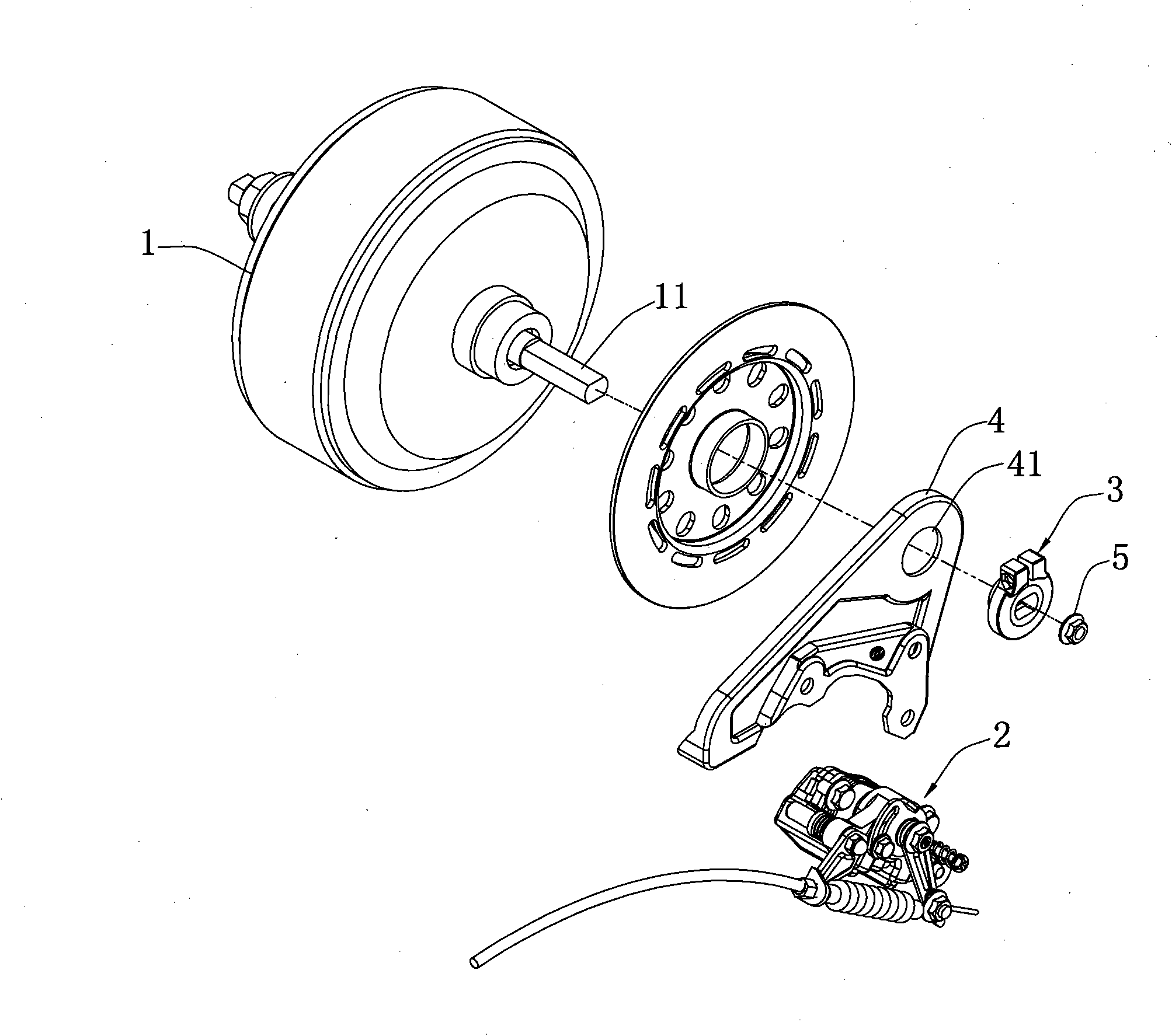
[0019] Such as figure 1 As shown, the present invention is a connection structure between a disc brake mounting plate and a hub motor shaft, including a disc brake assembly 2, a hub motor shaft 11 and a mounting plate for installing the disc brake assembly 2 on the hub motor shaft 11 4. The mounting plate 4 is provided with a mounting hole 41 for the hub motor shaft to pass through, the hub motor shaft 11 is provided with a positioning device, and the mounting plate 4 passes through the tightening mechanism 3 provided on the mounting hole 41 Lock on the positioning device.

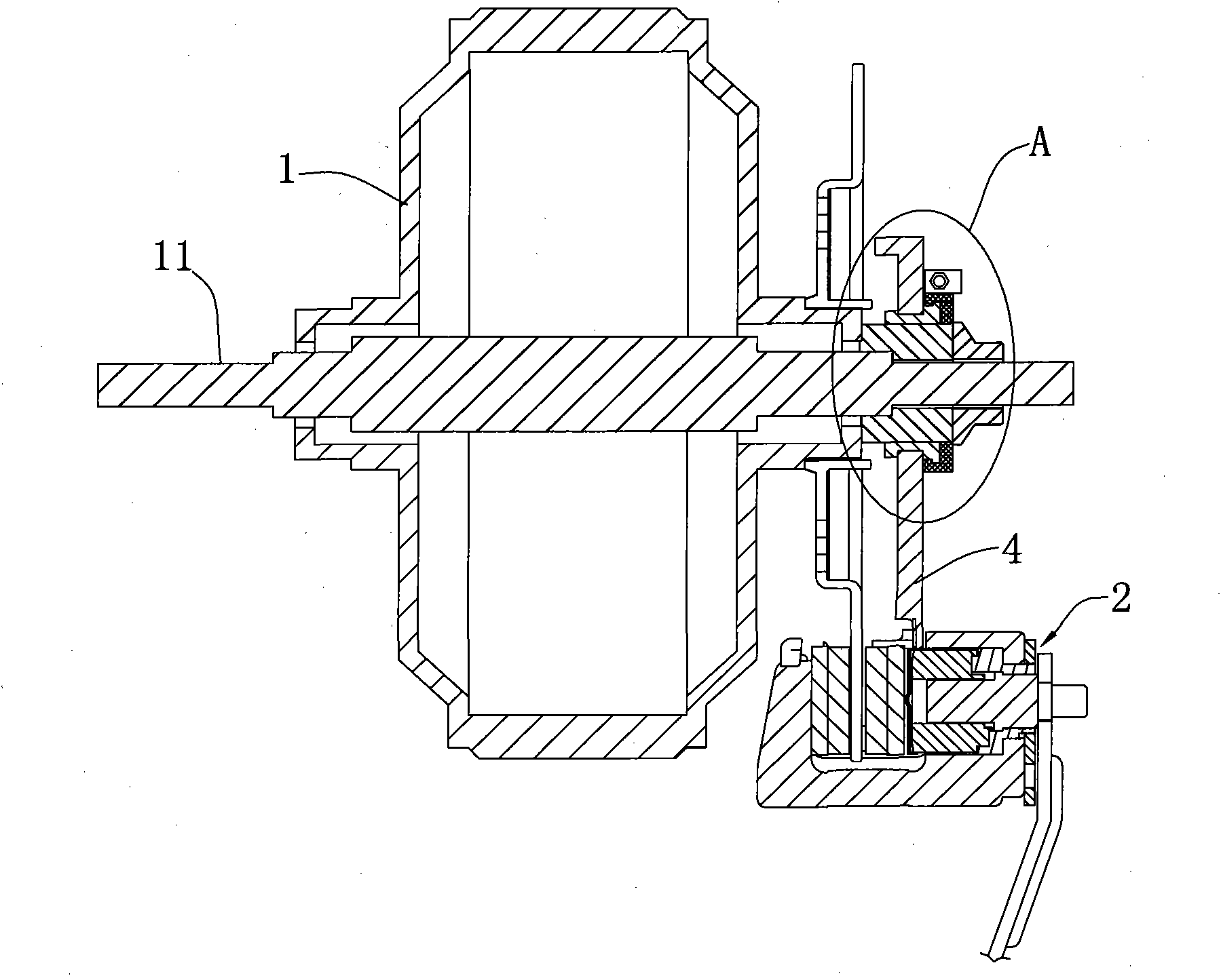
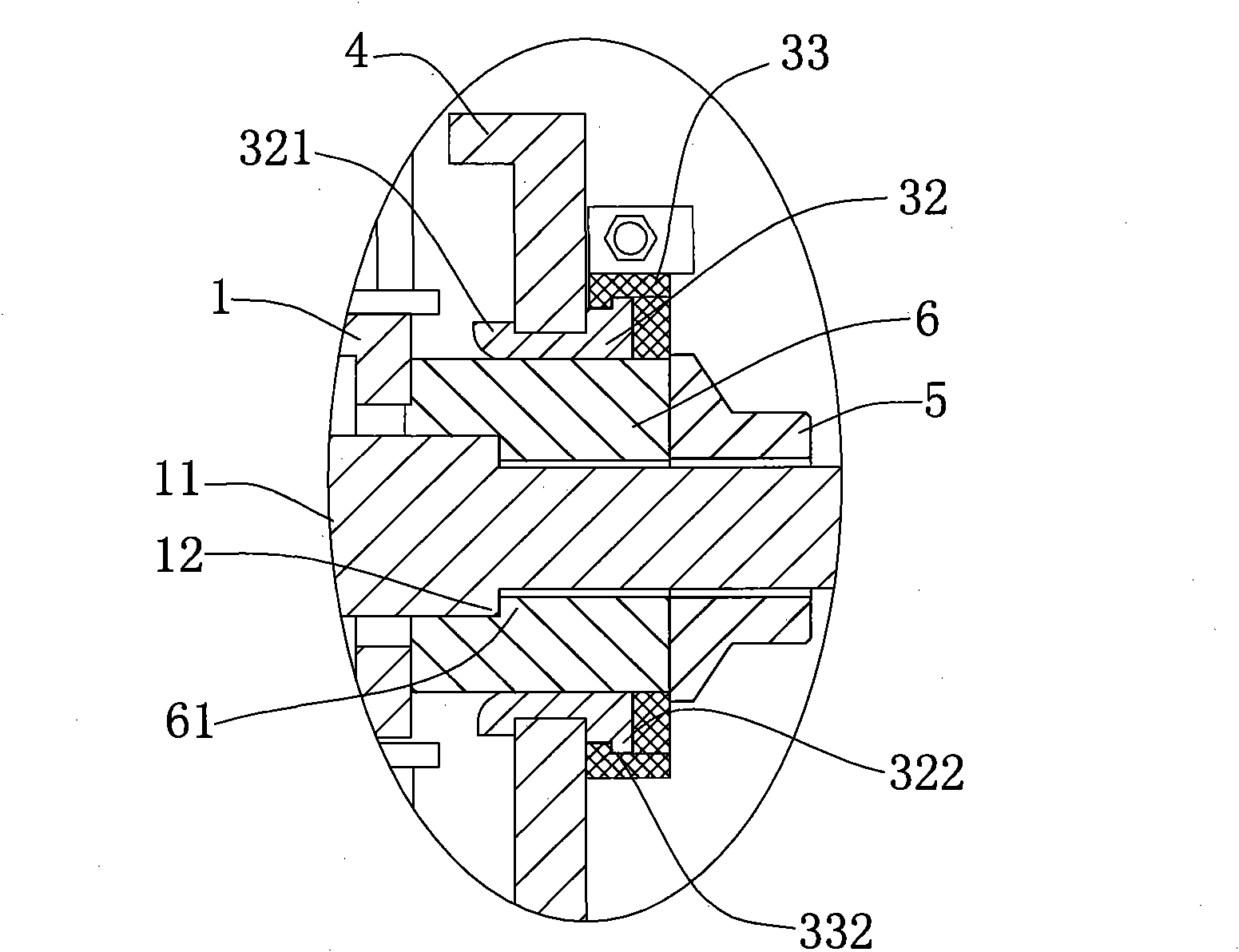
[0020] refer to Figure 2 to Figure 6 , a preferred embodiment of the present invention: the positioning device includes a shaft sleeve 6 and a lock nut 5 sleeved on the hub motor shaft 11, the shaft sleeve 6 is locked on the hub motor shaft 11 through the lock nut 5, and the shaft sleeve 6 The left end surface of the hub 1 abuts against the side of the hub 1; the hub motor shaft 11 is provided with a sh...


PUM


Abstract

The invention discloses an improved connection structure between a disk brake mounting board and a wheel hub motor shaft, the structure comprises a disk brake assembly, the wheel hub motor shaft and the mounting board for installing the disk brake assembly on the wheel hub motor shaft, the mounting board is provided with a mounting hole for the wheel hub motor shaft to go through, the wheel hub motor shaft is provided with a positioning device, and the mounting board is locked on the positioning device by a tightening mechanism which is arranged on the mounting hole. The structure solves the adjustment problem when the disk brake is connected with the wheel hub motor shaft and enables the installation of the disk brake to be more convenient and the brake performance to be stable and reliable.

Description

technical field [0001] The invention relates to a mechanical disc brake device, in particular to an improved structure for connecting a disc brake mounting plate and a wheel hub motor shaft applied to an electric vehicle. Background technique [0002] Service brakes have evolved from drum type, rim type to disc brake type, advancing with the times. Disc brakes have been widely installed on most motor vehicles due to their superior braking effect. Brakes, a safety and life-saving device, have no right to fail . Although the effect of disc brakes is good, the structure is complex and the installation requirements are relatively high. Disc brakes rely on the tension of the brake line to make the brake pads in the caliper rub against and clamp the disc to produce a braking effect. Therefore, the difference between the disc and the brake pads of the disc brake It is required to have a good enough parallelism, and the disc and the disc brake assembly are installed on the hub and ...

Claims


Application Information

Patent Timeline
Patent Type & Authority Patents(China)
IPC IPC(8): B60K7/00B60T1/06
Inventor 许志明许文涛
Owner CHANGXING HUAYI ELECTROMECHANICAL
Why Eureka
Try Eureka