
Gear crack propagation simulated wavelet extension finite element simulation analysis method

A technology of extended finite element and crack extension, applied in the field of finite element analysis, can solve problems such as low efficiency, discontinuity, and inability to jump material properties, and achieve the effect of high calculation efficiency and high calculation accuracy

Inactive Publication Date: 2012-01-25
BEIJING UNIV OF TECH
View PDF1 Cites 31 Cited by
  • Summary
  • Abstract
  • Description
  • Claims
  • Application Information

AI Technical Summary

Problems solved by technology

[0003] The traditional finite element method uses a continuous function as the shape function, which requires that the shape function inside the element is continuous and the material properties cannot jump. When dealing with discontinuous problems such as cracks, it is necessary to set the crack surface as the edge of the element, and set the crack tip as The nodes of the unit, and the high-density mesh division in the singular field of the discontinuity near the crack tip and the need to continuously re-mesh when simulating crack growth, this makes the finite element program design quite complicated. and extremely inefficient
The extended finite element method (XFEM), developed within the finite element framework, focuses on solving the discontinuity problem. Although it does not need to mesh the geometric or physical interface existing in the structure when dealing with the crack problem, it is for It is still difficult to deal with singularity problems such as cracks in engineering
The wavelet finite element method, which introduces the wavelet analysis theory into the finite element analysis, can solve the difficulties caused by the singularity of the crack tip region because of its multi-scale and multi-resolution characteristics, but it cannot reflect the growth of the crack

Method used


Image

  • Gear crack propagation simulated wavelet extension finite element simulation analysis method
  • Gear crack propagation simulated wavelet extension finite element simulation analysis method
  • Gear crack propagation simulated wavelet extension finite element simulation analysis method

Examples


Embodiment Construction

[0057] The present invention will be further described below in conjunction with the accompanying drawings and examples.

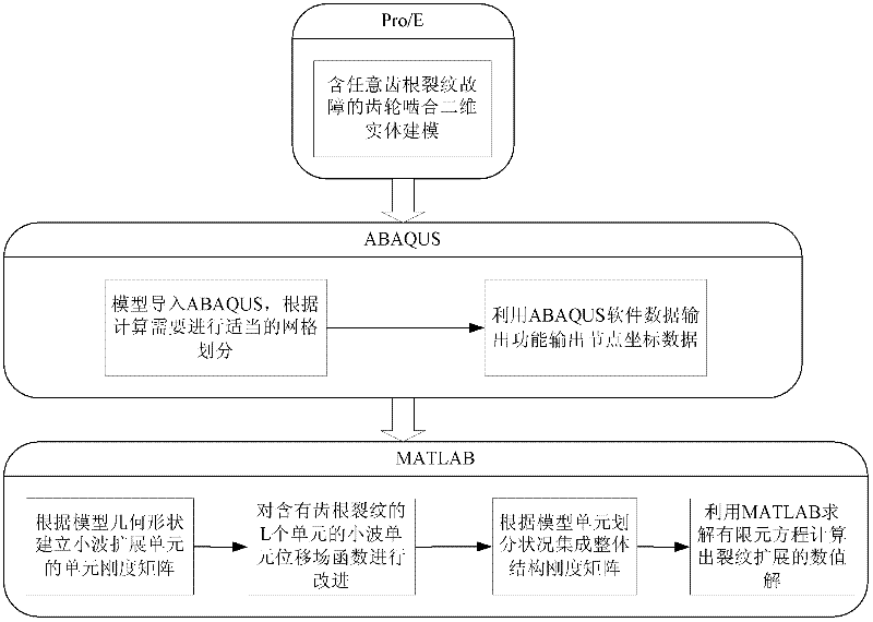
[0058] Such as figure 2 Shown is a schematic diagram of the workflow of this embodiment. It mainly consists of 3 parts, and the detailed steps are as follows.

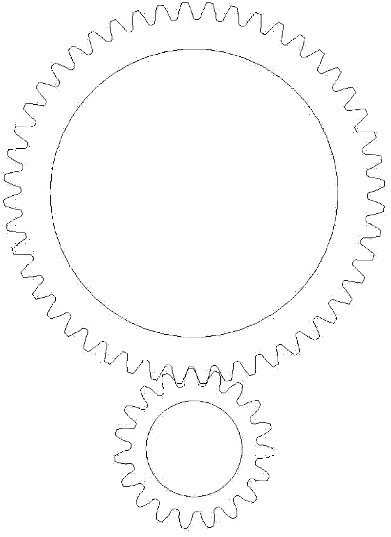
[0059] 1. Use Pro / E drawing software to draw a meshing model of a gear with a modulus of 2 and a number of teeth of 19 and another large gear, such as image 3 shown. According to the requirements, any form of crack fault can be added to the gear teeth, and the position, size, shape and other characteristics of the crack can be changed to simulate complex crack faults that are more in line with the actual situation. Figure 4 Shown is a hypothetical tooth with an illustrated crack failure at the root.

[0060] 2. Use ABAQUS to divide the finite element grid and output the grid node coordinates:

[0061] 1) Import the gear model drawn by Pro / E into ABAQUS and divide it to generate a gear model...


PUM


Abstract

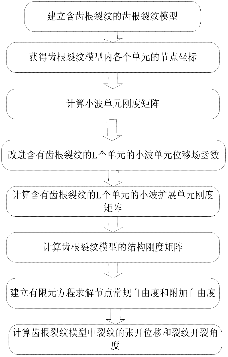
The invention relates to a finite element analysis method for crack propagation, in particular to a numerical value analysis method using wavelet extension as a new finite analysis unit. The method comprises the following steps that: based on a computer-aided drawing software, a gear meshing model containing any crack failure is built; the module is imported into a finite element analysis software ABAQUS, and geometric data of a finite element mesh is obtained by combination of ABAQUS meshing and data output functions; according to the obtained data, a mathematics-assisted calculation software is applied to a program to calculate the element stiffness matrix of a wavelet extension unit, and then according to the mesh of the analyzed structure, the overall stiffness matrix of an integratedstructure is arranged; and after boundary constraint conditions and loads are introduced, a finite element equation is solved to obtain the numerical value solution of crack propagation. In the invention, the growth conditions of cracks can be tracked, and the difficulty brought by highly concentrated stress is also solved; and the method has higher computational accuracy and higher computationalefficiency, and facilitates the study of fault diagnosis of mechanical equipment.

Description

technical field [0001] The invention relates to a finite element analysis method aimed at crack extension, and is a numerical analysis method using a new finite analysis unit of wavelet extension. Background technique [0002] Since the displacement and stress of the gear crack tip area contain Singularity (where r is the polar coordinate vector radius of a point near the crack tip), the gradient of the solution near the singular point in the crack is large, and there will be a sudden change, which makes it difficult for the traditional finite element method to obtain the numerical solution. [0003] The traditional finite element method uses a continuous function as the shape function, which requires that the shape function inside the element is continuous and the material properties cannot jump. When dealing with discontinuous problems such as cracks, it is necessary to set the crack surface as the edge of the element, and set the crack tip as The nodes of the unit, and ...

Claims


Application Information

Patent Timeline
IPC IPC(8): G06F17/50
Inventor 崔玲丽甄君伟张飞斌高立新张建宇
Owner BEIJING UNIV OF TECH
Learn More