
Plunger water pump and liquid control system thereof

A plunger and water pump technology, applied in the field of plunger water pump and its hydraulic control system, can solve the problems of loss of life and property, inability to deliver water in a timely and effective manner, and inability to meet the requirements of water consumption for fire fighting in super high-rise buildings, so as to prevent internal Drain, improve the effect of output flow and water pressure

Inactive Publication Date: 2012-01-25
XUZHOU HEAVY MASCH CO LTD
View PDF8 Cites 8 Cited by
  • Summary
  • Abstract
  • Description
  • Claims
  • Application Information

AI Technical Summary

Problems solved by technology

[0003] In the prior art, there are mainly two types of fire pumps used for water supply: centrifugal pumps and plunger pumps; limited by their own structures, both of them usually can only send water to a height of about 100 meters, which occurs in super high-rise buildings. After a fire, due to insufficient water supply pressure and flow, the water source cannot be delivered in a timely and effective manner, so that the spread of the fire cannot be controlled, often resulting in a very large loss of life and property
Among them, the centrifugal water pump has leakage and backflow problems during the working process. As the outlet pressure increases, the leakage and return flow increase synchronously. It is difficult for the outlet pressure to reach the standard that the rated pressure of the high-pressure fire pump is not less than 4.0MPa, and the work efficiency is reduced; However, the working principle of the plunger pump limits its output flow generally to no more than 10L / s, which cannot meet the water consumption requirements for fire fighting in super high-rise buildings.

Method used


Image

  • Plunger water pump and liquid control system thereof
  • Plunger water pump and liquid control system thereof
  • Plunger water pump and liquid control system thereof

Examples


Embodiment Construction

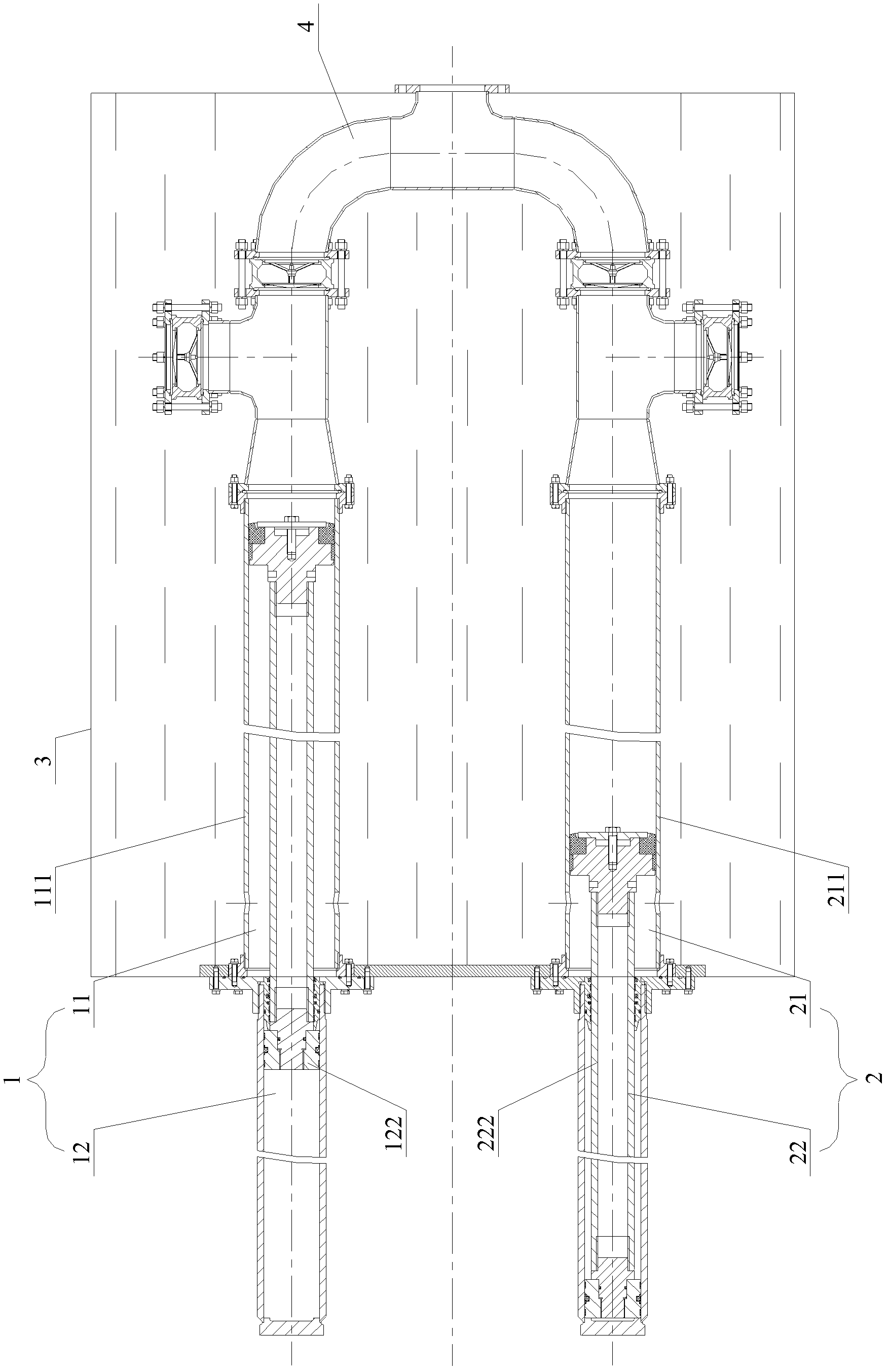
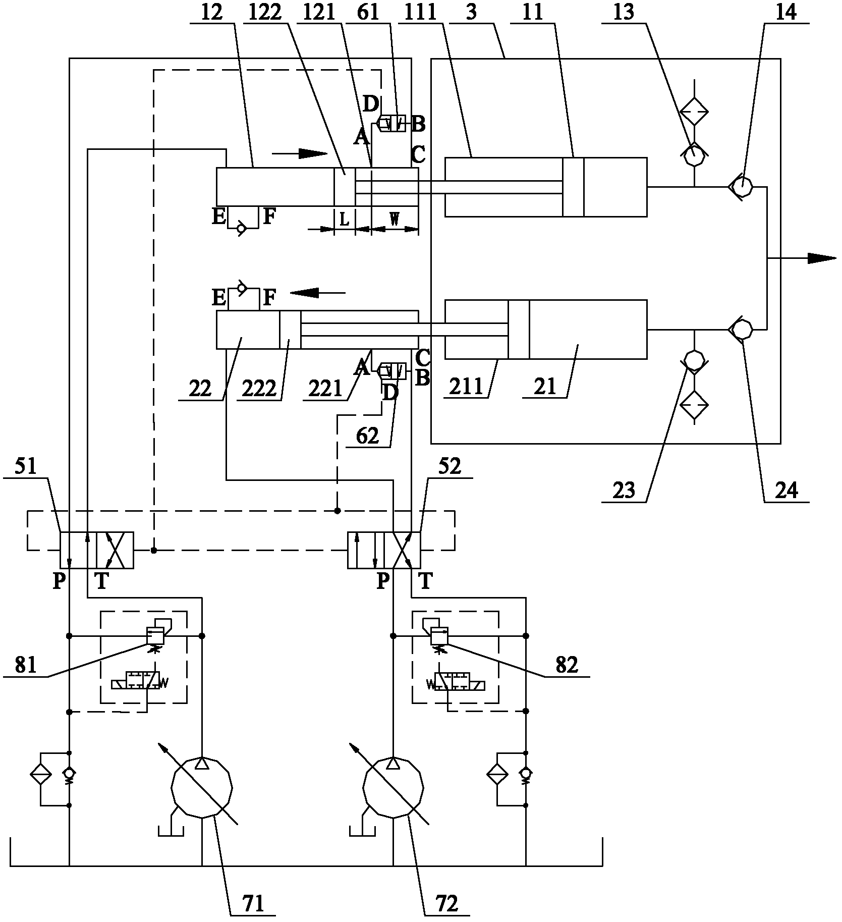
[0025] The core of the present invention is to provide a hydraulically controlled double-plunger water pump with optimized structure, which includes two plunger groups composed of a water cylinder and an oil cylinder. The water outlets of the cylinder barrels of the water cylinders are all connected with a water inlet check valve for one-way conduction from the outside to the inner cavity of the cylinder barrel, and a one-way water outlet valve for one-way conduction from the inner cavity of the cylinder barrel to the outer water outlet; the two oil cylinders It is configured to expand and contract alternately under the control of the control valve. Compared with the prior art, the invention can reliably increase the output pressure and flow rate of the water pump, so as to meet the fire-fighting requirements of super high-rise buildings.

[0026] Without loss of generality, this embodiment will be described in detail below in conjunction with the accompanying drawings.

[00...


PUM


Abstract

The invention discloses a plunger water pump. The plunger water pump provided by the invention comprises two plunger groups which are composed of water cylinders and oil cylinders, a water cylinder piston and an oil cylinder piston of each plunger group are synchronously displaced, a water gap of each water cylinder barrel is provided with a water inlet one-way valve which is in one-way conduction with a cylinder tube cavity from the outside and a water outlet one-way valve which is in one-way conduction with the cylinder tube cavity from the cylinder tube cavity to the outside; and two oil cylinders are alternately stretched under the control of a control valve. The plunger water pump provided by the invention breaks through a traditional water pump structural principle, two oil cylinders are adopted to alternately move and retreat, thereby driving two water cylinders pistons to alternately move, and further the switch of two working conditions is respectively realized; compared with the prior art, the plunger water pump is capable of effectively improving the output flow and the water utilization pressure on the basis of the continuous no-interval foundation; and the invention also provides a liquid control system of the plunger water pump.

Description

technical field [0001] The invention relates to construction machinery technology, in particular to a plunger water pump and its hydraulic control system. Background technique [0002] As the overall height of commercial and civil super high-rise buildings continues to rise, one of the difficulties in the fire protection system is the difficulty of water supply. As we all know, the fire-fighting water provided by most fire-fighting water sources needs to be pressurized by fire-fighting water pumps to meet the requirements for water pressure and water volume when extinguishing fires. For example, taking a mobile equipment fire truck as an example, it is usually equipped with a fire pump to provide pressurized water for fire extinguishing terminals such as fire water cannons and fire water cannons. Obviously, a fire pump with good performance plays a decisive role in the formulation of fire extinguishing tactics and the implementation of fire extinguishing methods. [0003] ...

Claims


Application Information

Patent Timeline
IPC IPC(8): F04B9/113
CPCF04B9/1172F04B23/06
Inventor 史先信冯瑜徐小东赵阳光
Owner XUZHOU HEAVY MASCH CO LTD
Learn More