Lever type laser detection device for material tension

A laser detection and lever-type technology, applied in the direction of measuring devices, optical devices, and analyzing materials, can solve the problems of unfavorable on-site teaching, small working space, and large noise, and achieve intuitive and open test process, easy installation and operation, The effect of simple structure

Inactive Publication Date: 2012-01-18
CHONGQING VOCATIONAL INST OF ENG
View PDF4 Cites 8 Cited by
  • Summary
  • Abstract
  • Description
  • Claims
  • Application Information

AI Technical Summary

Problems solved by technology

Existing instruments and equipment generally include mechanical, electronic and optical structures, all of which have the disadvantages of small working space and small viewing window, such as dial gauges, millivoltmeters, and monocular telescopes, which can only be used by a single person. Read, other participants in the test passively accept, thus affecting the learning effect
[0003] At the same time, the existing stretching equipment has the characteristics of large size and high noise, while the detection equipment of the prior art must be installed in the stretching equipment to read nearby. Due to the large noise, it is not conducive to on-site teaching, and There are also some auxiliary equipment such as wires arranged on site, which is not conducive to group on-site teaching; as for remote observation equipment such as telescopes, which are affected by light and are easily disturbed by the outside world, they are suitable for single-person operation and not suitable for group teaching.
Moreover, the structure and use of the above-mentioned detection equipment are relatively complicated, and only one standard moment of the specimen can be tested during the experiment, which has limitations.

Method used


Image

  • Lever type laser detection device for material tension
  • Lever type laser detection device for material tension
  • Lever type laser detection device for material tension

Examples


Embodiment Construction

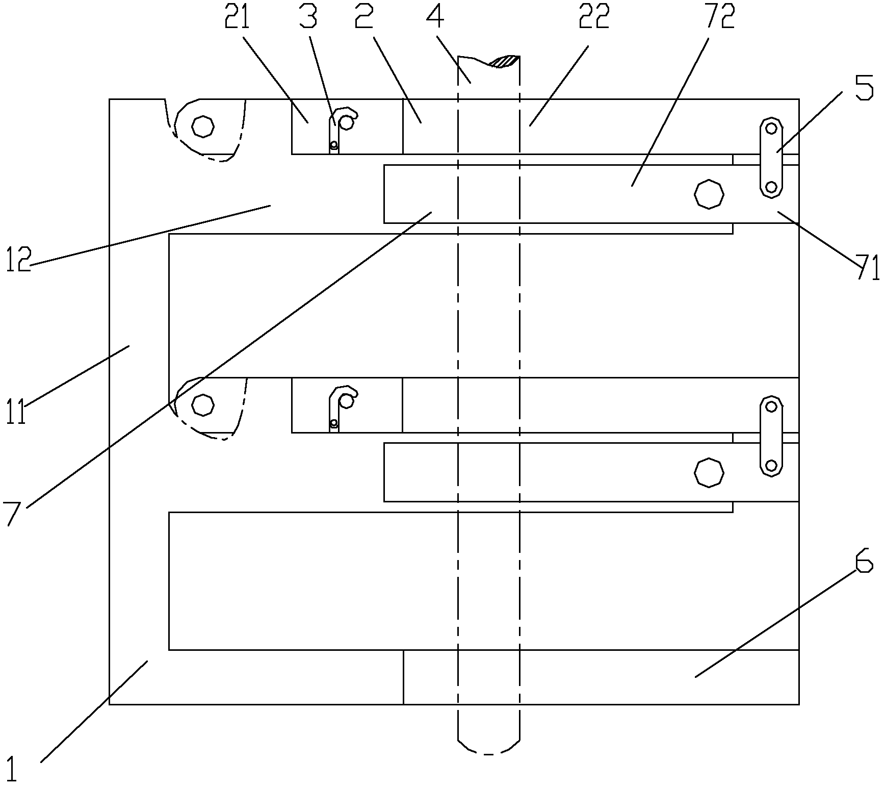
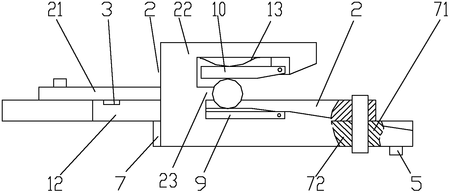
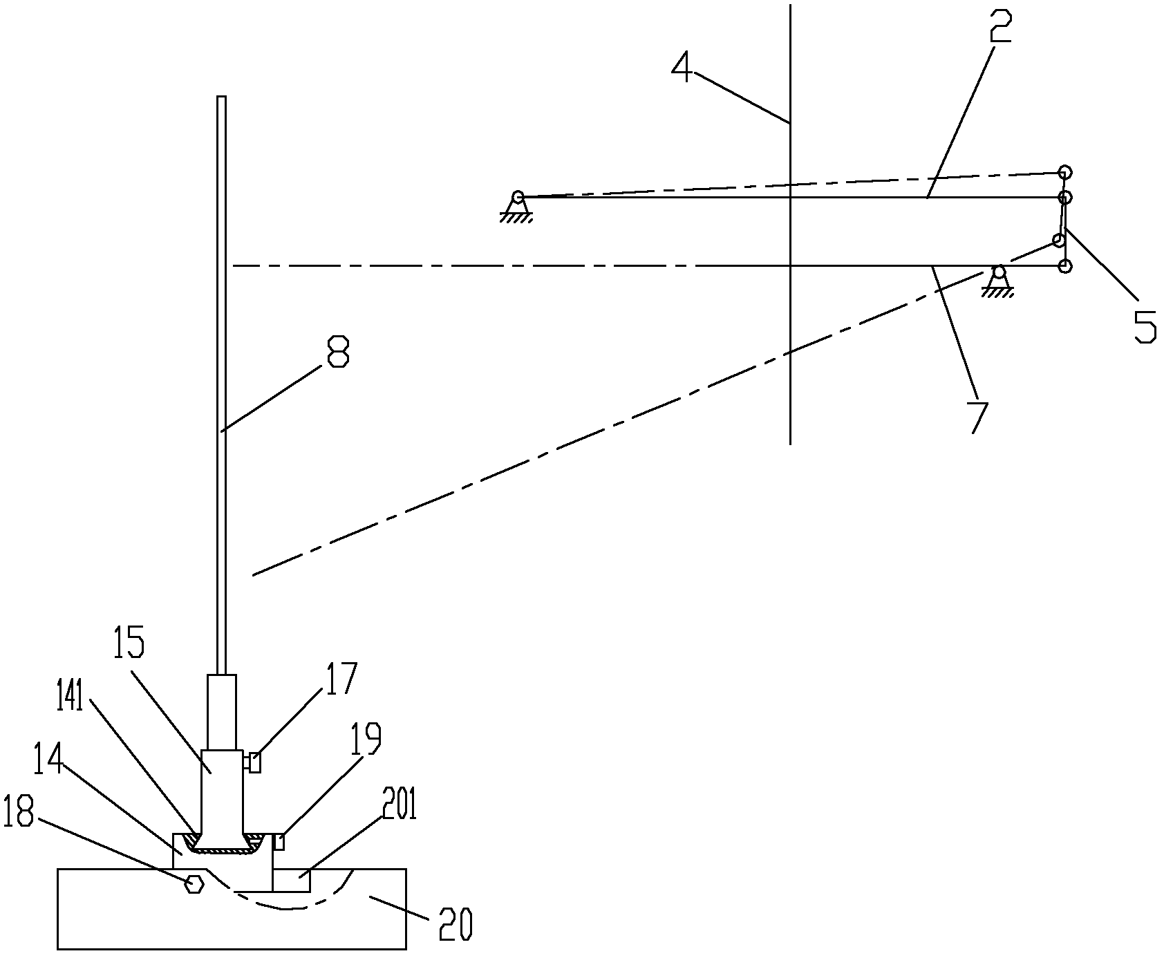
[0024] figure 1 It is a schematic diagram of the structure of the present invention, figure 2 for figure 1 View along direction A, image 3 It is a schematic diagram of the present invention, as shown in the figure: the material stretching lever type laser detection device of this embodiment includes a support frame 1 and a laser detection assembly;

[0025] The laser detection assembly is at least two groups arranged side by side along the stretching direction of the test piece. In this embodiment, there are two groups; including the laser 7, the gauge fork 2 and the connecting rod 5, the casing of the laser 7 is hinged to the support frame 1 to form a lever structure , one end of the gauge fork 2 is hinged to the support frame 1 in such a way that the gauge fork 2 can rotate along the stretching direction of the test piece 4, that is, it can be hinged by a spherical hinge, or it can be perpendicular to the stretching direction of the test piece. The three hinge shafts ar...


PUM


Abstract

The invention discloses a lever type laser detection device for material tension. The lever type laser detection device comprises a support frame and laser detection assemblies, wherein at least two groups of laser detection assemblies are arranged in parallel along the tensile direction of a test piece; staff gauges for reading laser line corners are correspondingly arranged on laser transmission lines of lasers of the laser detection assemblies; and a gauge length setting fork is arranged on the support frame. According to the lever type laser detection device disclosed by the invention, a structure with a plurality of lasers is arranged on the test piece and is twisted for a certain angle along the tension of the test piece; the deflection angle of the transmitted laser light path is read by the staff gauge; and material tensile strain multipoint data are obtained according to respective reading of each laser and the material tensile Hooke's law is verified. Therefore, the lever type laser detection device can be used for testing multiple points of the test piece; the test process is direct-viewed and open, thus the test process and the change of parameters can be clearly seen by people on the scene and the lever type laser detection device is suitable for classroom teaching and testing. The invention has the advantages of simple structure, easiness for disassembly, assembly and operation and lower test cost compared with that of equipment in the prior art.

Description

technical field [0001] The invention relates to teaching experiment equipment, in particular to a laser detection device for material tensile strain detection. Background technique [0002] In the material mechanics experiment, in order to measure the deformation of the test piece within the proportional limit, special instruments with high sensitivity and precision are needed. Existing instruments and equipment generally include mechanical, electronic and optical structures, all of which have the disadvantages of small working space and small viewing window, such as dial gauges, millivoltmeters, and monocular telescopes, which can only be used by a single person. Read, other personnel involved in the detection passively accept, thus affecting the learning effect. [0003] At the same time, the existing stretching equipment has the characteristics of large size and high noise, while the detection equipment of the prior art must be installed in the stretching equipment to re...

Claims


Application Information

Patent Timeline
Patent Type & Authority Applications(China)
IPC IPC(8): G01N3/08G01N3/02G01B11/02G09B23/10
Inventor 张明学柳琳顾佳
Owner CHONGQING VOCATIONAL INST OF ENG
Why Eureka
Try Eureka