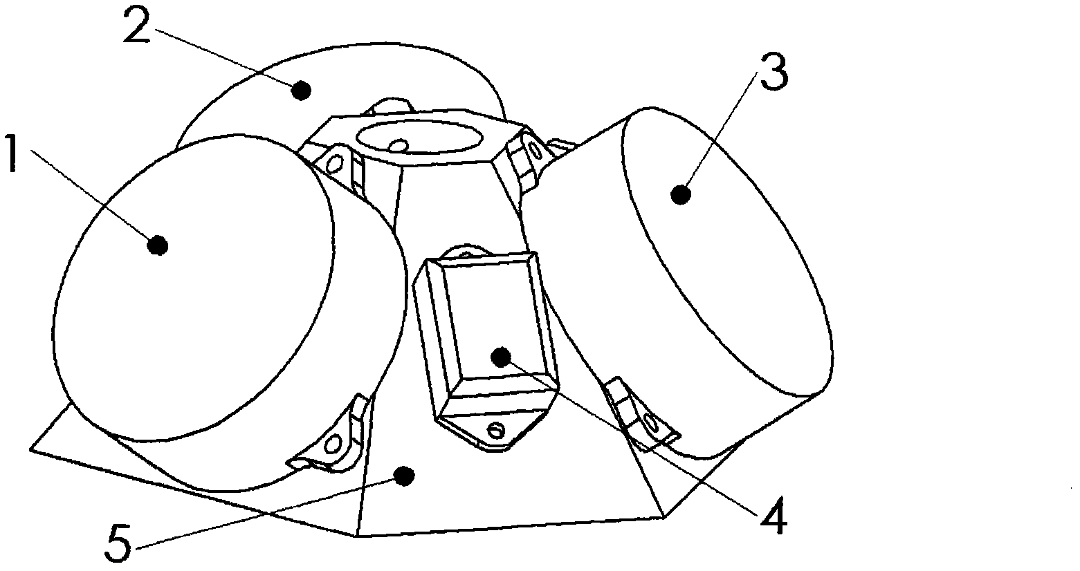
Sensor tilting inertia measurement unit structure
An inertial measurement component and sensor technology, applied in the field of inertial navigation, can solve the problems of geometric center offset, inertial measurement component size, space and weight exceeding usage requirements, and space waste utilization and other problems
- Summary
- Abstract
- Description
- Claims
- Application Information
AI Technical Summary
Problems solved by technology
Method used
Image

Examples
Embodiment
[0049] The present invention is described in detail by taking the design of an inertial measurement component for a strapdown inertial navigation component of a missile-borne strapdown guidance system as an example. The maximum external dimension of the inertial measurement component is required to be Φ150mm×60mm; the maximum angular velocity along the missile roll axis is 1000° / s; the maximum acceleration rate along the missile roll axis is 15g; the maximum angular velocity of the other axes is 300° / s, The maximum acceleration in other axial directions is 8g; suppose a gyro is selected, its maximum external dimension is Φ68mm×20mm, and its maximum dynamic range is 600° / s; an accelerometer is selected, its maximum external dimension is 36mm×18mm×12mm, and its maximum dynamic range is 10g.
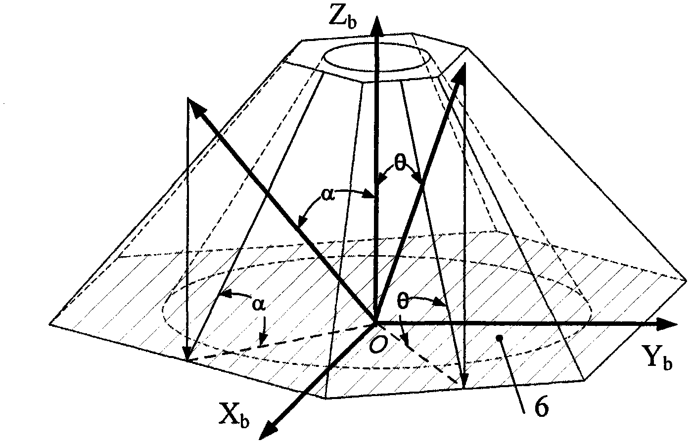
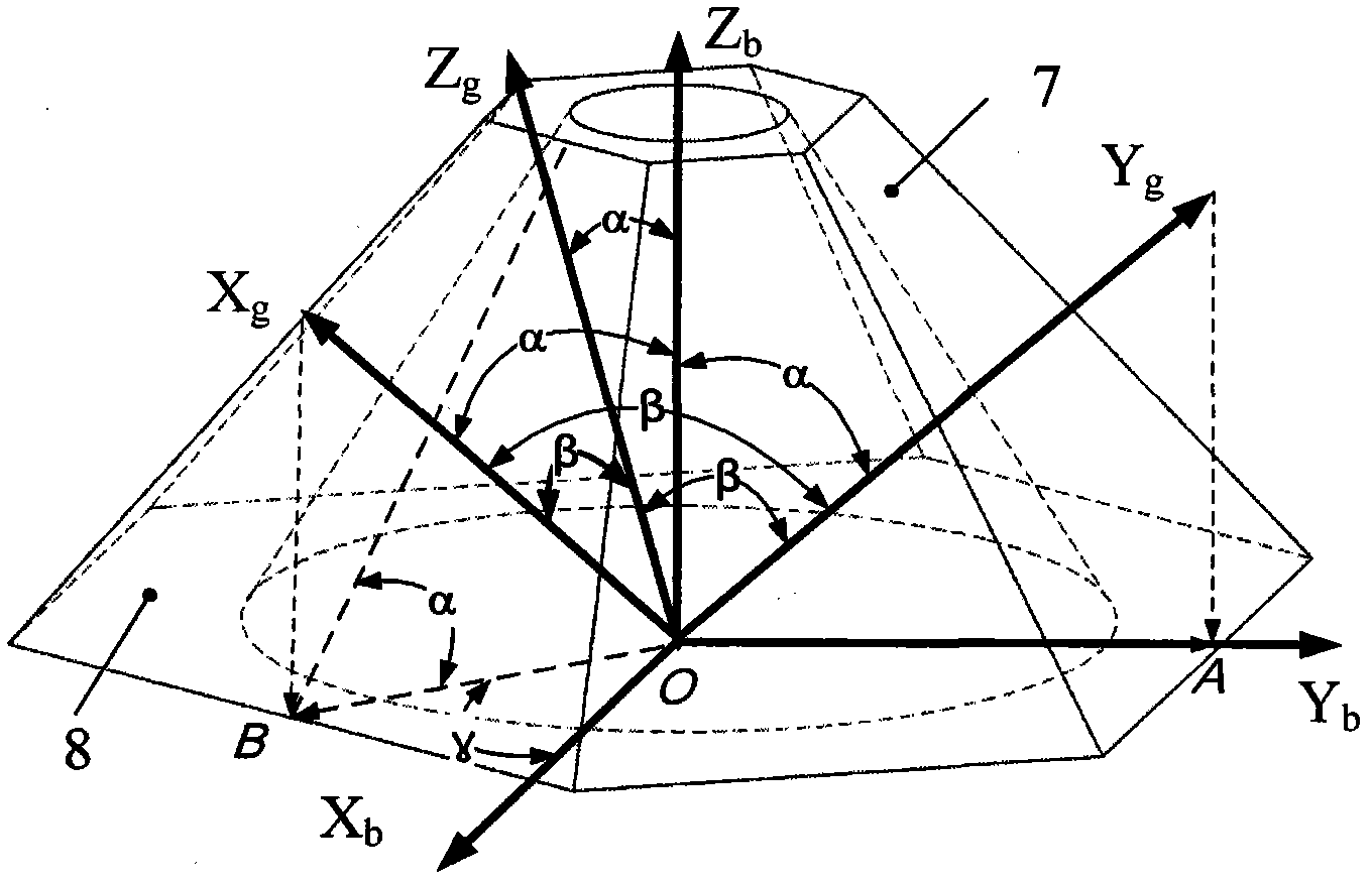
[0050] (1) The structure of the bracket
[0051] The mounting surface of the bracket is the bottom surface of the bracket, and the normal line of the mounting surface of the bracket coinci...
PUM
 Abstract
Description
Claims
Application Information
 - Generate Ideas
- Intellectual Property
- Life Sciences
- Materials
- Tech Scout
- Unparalleled Data Quality
- Higher Quality Content
- 60% Fewer Hallucinations
Browse by: Latest US Patents, China's latest patents, Technical Efficacy Thesaurus, Application Domain, Technology Topic, Popular Technical Reports.
© 2025 PatSnap. All rights reserved.Legal|Privacy policy|Modern Slavery Act Transparency Statement|Sitemap|About US| Contact US: help@patsnap.com