
Water jet cutting machine and jet generation device thereof

A generation device and jet flow technology, applied in metal processing, etc., can solve the problems of equipment use, high maintenance costs, high requirements for plunger rod materials, short plunger rod strokes, etc., achieve significant energy saving effects, reduce material requirements, The effect of reducing the failure rate and wearing parts

Inactive Publication Date: 2012-01-18
BEIJING CLEVER DELI MACHINERY EQUIP
View PDF6 Cites 1 Cited by
  • Summary
  • Abstract
  • Description
  • Claims
  • Application Information

AI Technical Summary

Problems solved by technology

However, the volume of the existing direct-drive three-plunger high-pressure water jet generating device is relatively small, and the plunger rod is very thin (8mm in diameter) and the stroke is very short (40mm). The number of reciprocating movements of the plunger rod must reach 750 times per minute. Therefore, the direct-drive three-plunger high-pressure water jet generating device has high requirements on the hardness and wear resistance of the plunger rod and the material of the high-pressure sealing ring on the plunger rod. , it is difficult to manufacture, and the cost of equipment use and maintenance is relatively high

Method used


Image

  • Water jet cutting machine and jet generation device thereof
  • Water jet cutting machine and jet generation device thereof
  • Water jet cutting machine and jet generation device thereof

Examples


no. 1 example

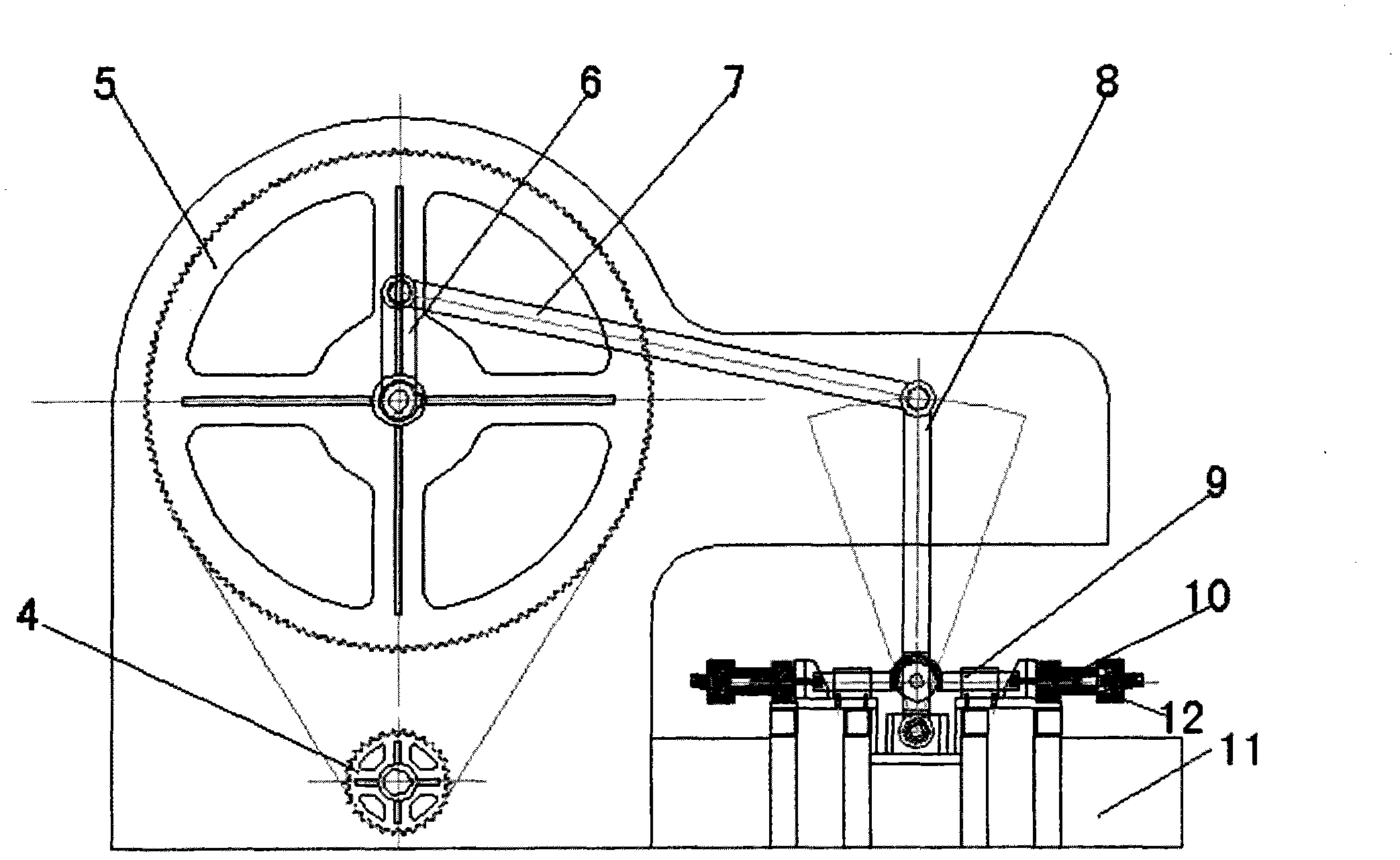
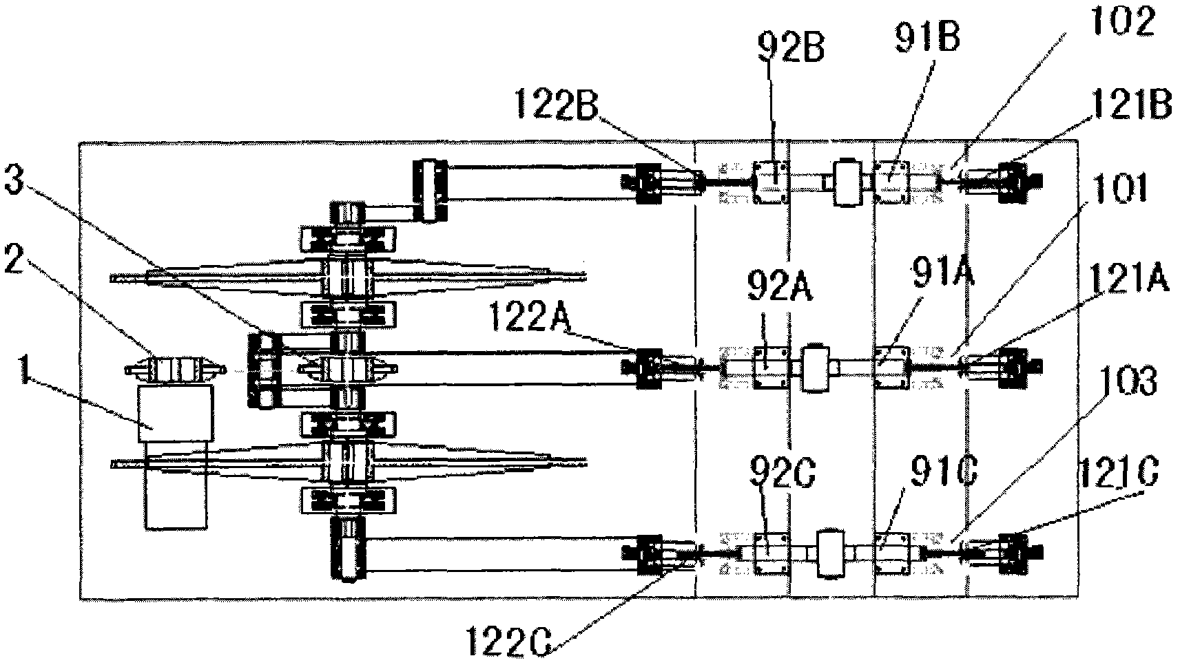
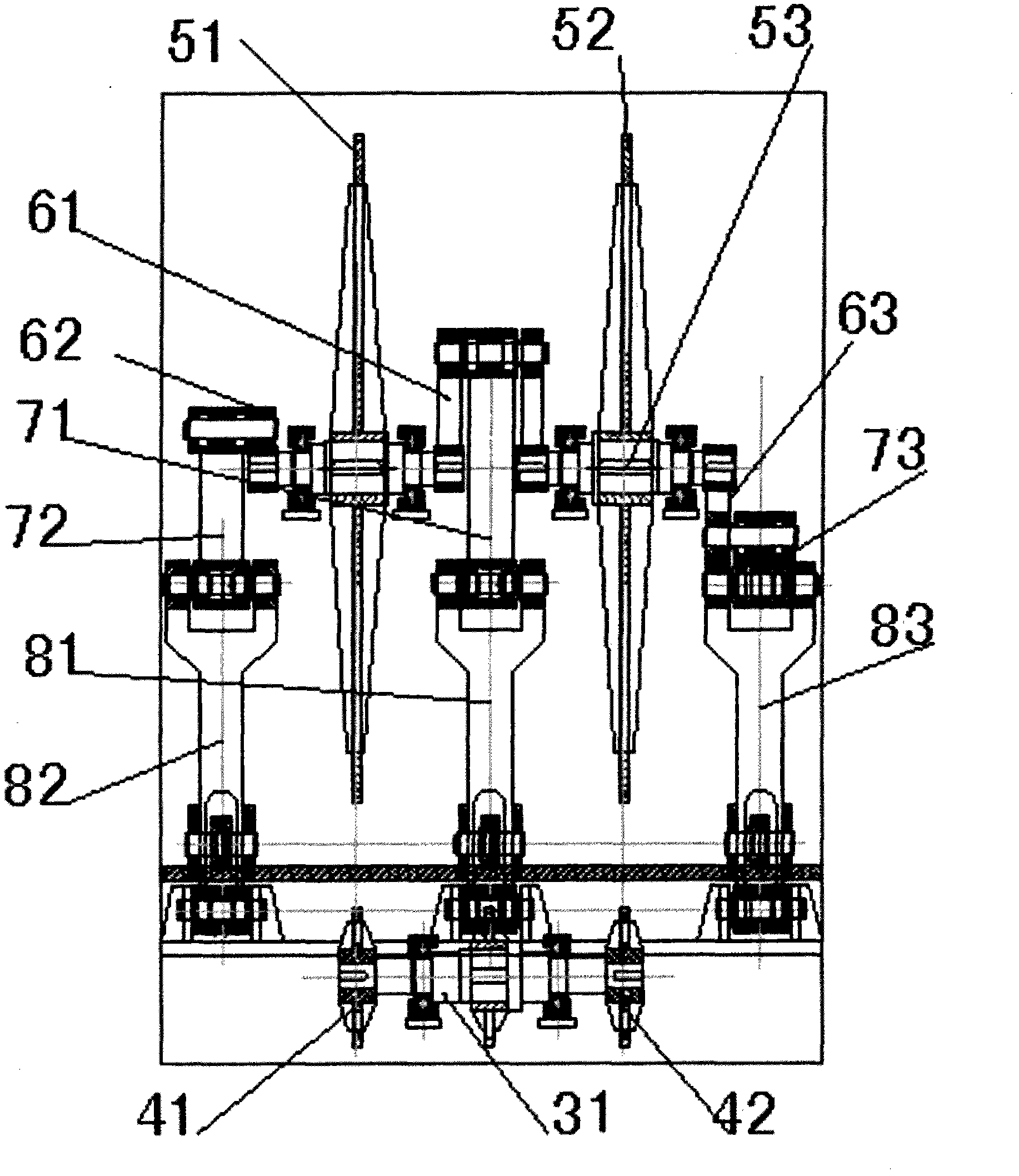
[0034] figure 1 , 2 , 3 respectively show a front view, a top view, and a left view of the jet flow generating device according to the first embodiment of the present invention.

[0035] The jet generating device includes a frame 11, a driving device 1 arranged on the frame 11, a driving wheel 2 arranged on the driving device 1, a first transmission shaft 31 arranged on the frame 11, a first transmission shaft 31 arranged on the first transmission shaft 31 The driving wheel 3 and the driven wheel 4 (the driven wheel 4 includes the first driven wheel 41 and the second driven wheel 42), the work wheel 5 arranged on the frame 11 (the work wheel includes the first work wheel 51 and the second work wheel 51) Two working wheels 52), the second transmission shaft 53, the rocking arm 6 that is arranged on the working wheel 5 (the rocking arm 6 includes the first rocking arm 61, the second rocking arm 62 and the third rocking arm 63), connecting rod 7 , Working lever 8, push rod 9, ...

no. 2 example

[0064] as attached Figure 5 , 6 , which shows the jet flow generating device of the second embodiment of the present invention. Wherein, the same or similar components as in the first embodiment are identified by the same or similar reference numerals.

[0065] When the user needs a small flow (such as less than 4 liters / min and pressure: 55000Psi), the high-torque eccentric wheel in the jet generating device of the first embodiment of the present invention can be used to directly push three plunger rods to generate high-pressure water jets. Mechanism; also can adopt the working lever structure in the jet flow generating device of the first embodiment of the present invention to realize the above function.

[0066] In the second embodiment, the jet flow generating device includes a frame, a driving device 1 arranged on the frame, a driving wheel 2 arranged on the frame, a driving wheel 3 and a driven wheel 4 arranged on the driving wheel, and The work wheel 5 on the frame,...


PUM


Abstract

The invention discloses a water jet cutting machine and a jet generation device thereof; the jet generation device comprises a frame, a driving device arranged on the frame, an acting wheel which is arranged on the frame and is rotated under the driving of the driving device, and a pressurization component, wherein the pressurization component comprises a rocker arm, a connecting rod, a push rod and a pressurization part; the rocker arm is arranged on the acting wheel and is rotated with the acting wheel, and the rocker arm drives the push rod to act through the connecting rod, the push rod is connected with a plunger rod of the pressurization part so as to drive the plunger rod to move; the pressurization part is provided with an output port for outputting the jet. The water jet cutting machine and the jet generation device thereof have larger flow and higher pressure, and meanwhile can obviously save energy.

Description

technical field [0001] The invention relates to a water cutting machine and a jet flow generating device thereof, in particular to an ultra-large flow and ultra-high pressure water cutting machine and a jet flow generating device thereof. Background technique [0002] Existing water cutting machines are all equipped with jet generating devices, and the existing ultra-high pressure water jet generating devices are mainly divided into two plunger high pressure water jet generating devices and three plunger high pressure water jet generating devices. [0003] Two-plunger high-pressure water jet generating device such as Figure 7A As shown, its working principle is to use the hydraulic system to push two plunger rods to make linear reciprocating motions in two hydraulic cylinders, compress the water and shoot it through a nozzle with a diameter of only 0.22-0.35mm, thereby generating a high-speed motion. water jet. [0004] The performance indicators of the two-plunger high-pr...

Claims


Application Information

Patent Timeline
Patent Type & Authority Applications(China)
IPC IPC(8): B26F3/00
Inventor 陈益鸿赵国明
Owner BEIJING CLEVER DELI MACHINERY EQUIP
Learn More