
Squirrel-cage rotor

A squirrel-cage rotor and rotor lamination technology, which is applied in the manufacture of motor generators, electrical components, electromechanical devices, etc., can solve the problems of slow starting speed and heavy weight of all-copper squirrel-cage rotors

Active Publication Date: 2012-01-11
SIEMENS AG
View PDF7 Cites 17 Cited by
  • Summary
  • Abstract
  • Description
  • Claims
  • Application Information

AI Technical Summary

Problems solved by technology

In addition, the all-copper squirrel-cage rotor is relatively heavier and thus has a slower starting speed than the squirrel-cage rotor with aluminum short-circuit rings disclosed in DE 43 08 683 A1

Method used


Image

  • Squirrel-cage rotor
  • Squirrel-cage rotor
  • Squirrel-cage rotor

Examples


Embodiment Construction

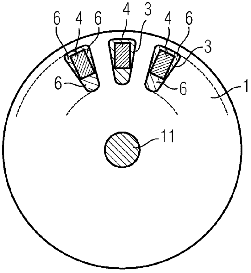
[0040] figure 1 An embodiment with a hybrid-structure squirrel-cage rotor for an asynchronous machine. The figure shows the laminated rotor core 1 of the asynchronous motor, which is shrink-fitted on the shaft body 11 . To manufacture such a squirrel-cage rotor, it is first necessary to insert conductors 4 , preferably made of copper, into the slots 3 of the laminated rotor core 1 . As shown, the cross-section of the conductor 4 is smaller than the cross-section of the slot 3 . Therefore, after the conductor 4 (in the form of a copper strip) is inserted, there will still be a residual section in the slot 3 .

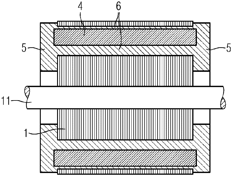
[0041] The next step in manufacturing a squirrel cage rotor is the die casting process. This process produces short-circuit rings whose end faces are in contact with the copper strips, while filling the remaining space in the groove 3 with melt. After the aluminum melt has hardened, aluminum features 6 are formed in the remaining cross-sectional area inside the groov...


PUM


Abstract

he invention relates to a squirrel-cage rotor for an asynchronous machine. In order to increase the electrical efficiency for a cage rotor composed of two materials, the cage rotor comprises a rotor core (1) having grooves (3), end rings (5) of a first material that are cast onto the rotor core on the end face, and conductors (4) that are arranged in the grooves and that are made of a second material that has a specific electric conductance that is higher than the specific electric conductance of the first material, wherein the conductors (4) comprise a coating (8) made of a coating material on the surface of the conductors, wherein the coating adjoins the second material of the conductors (4) by means of a first alloy layer (2) made of the second material and the coating material and adjoins the cast first material by means of a second alloy layer (9); made of the first material and the coating material.

Description

technical field [0001] The invention relates to a squirrel-cage rotor for an asynchronous machine according to the preamble of claim 1 . The invention also relates to a method of manufacturing a squirrel-cage rotor with the features stated in the preamble of claim 9 . Background technique [0002] A squirrel-cage rotor of this type is known from DE 43 08 683 A1. The rotor consists of a laminated iron core with slots into which copper shorting bars are first inserted. Connect the ends of these copper strips with a shorting ring. These short-circuit rings are made of aluminum by die-casting. When casting the short-circuit ring, the residual cross-section created by inserting the copper strips in the groove is filled with aluminum, thereby connecting the short-circuit ring to the die-cast condition formed in the area of ​​the remaining cross-section. [0003] Copper has a much higher electrical conductivity than aluminium, so that the efficiency of an asynchronous motor mad...

Claims


Application Information

Patent Timeline
Patent Type & Authority Applications(China)
IPC IPC(8): H02K15/00H02K17/16
CPCH02K17/205H02K17/165Y10T29/49012H02K17/20
Inventor 克劳斯·米特内延斯·库尔特米夏埃尔·米勒诺贝特·韦纳
Owner SIEMENS AG
Learn More