
Annealing apparatus

A technology of annealing device and furnace body, which is applied in the direction of lighting and heating equipment, furnace components, furnace types, etc., can solve the problems of short service life of the conveying device, and achieve the effect of long-term and long-term realization

Active Publication Date: 2015-01-14
IHI CORP +1
View PDF8 Cites 0 Cited by
  • Summary
  • Abstract
  • Description
  • Claims
  • Application Information

AI Technical Summary

Problems solved by technology

[0012] However, the conveyor belt part of the above-mentioned conveying device is arranged inside the furnace body, so the conveyor belt part is always exposed to the heating environment of the furnace body.
[0013] Therefore, in the conventional annealing device, there is a problem that the life of the conveying device having the conveying belt portion that grips and conveys the sheet is short.

Method used


Image

  • Annealing apparatus
  • Annealing apparatus
  • Annealing apparatus

Examples


Embodiment Construction

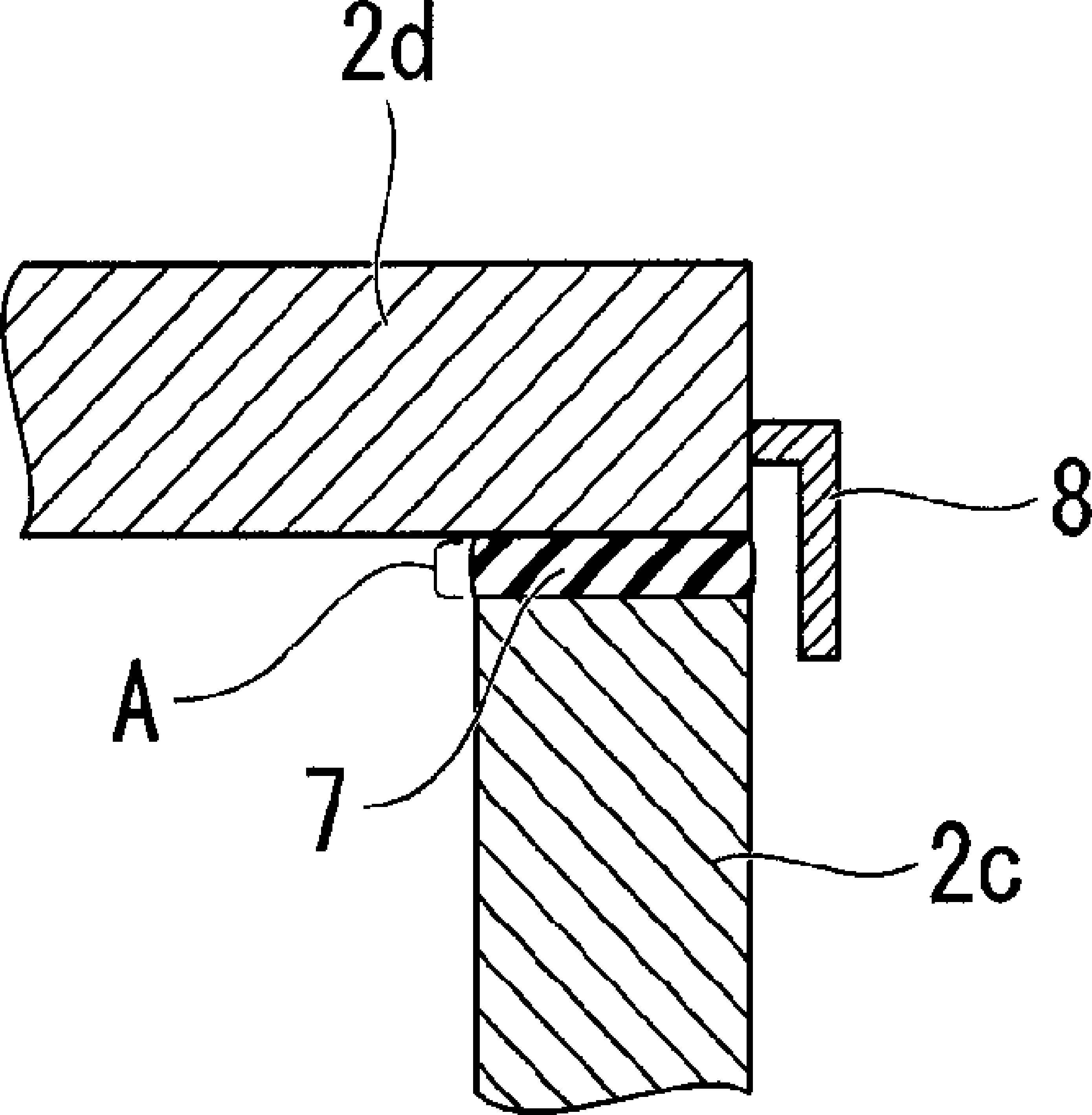
[0026] Below, refer to Figures 1 to 4 One embodiment of the annealing apparatus of the present invention will be described. In addition, in the following description, the scale of each member is changed suitably so that each member may be recognizable in size.

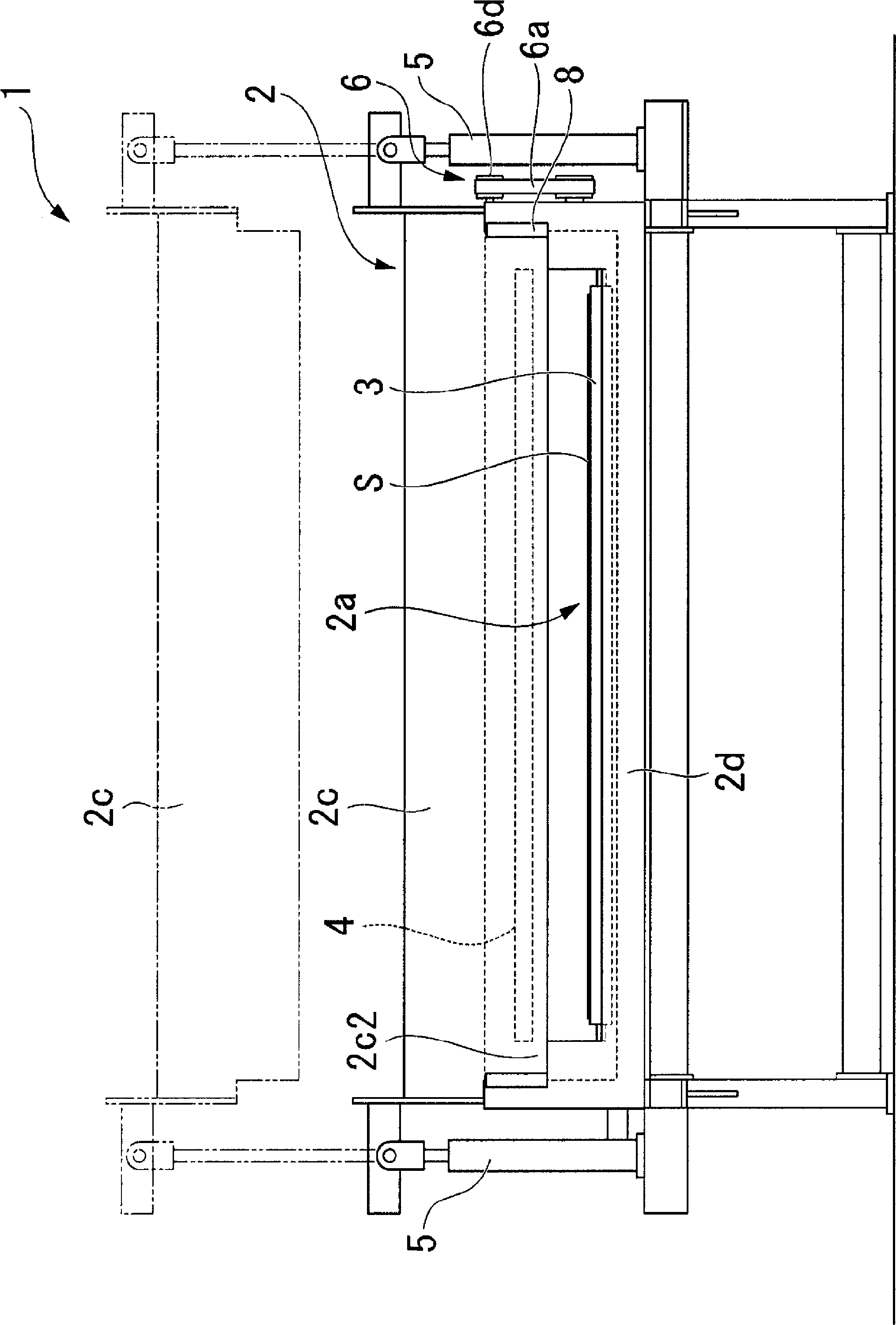
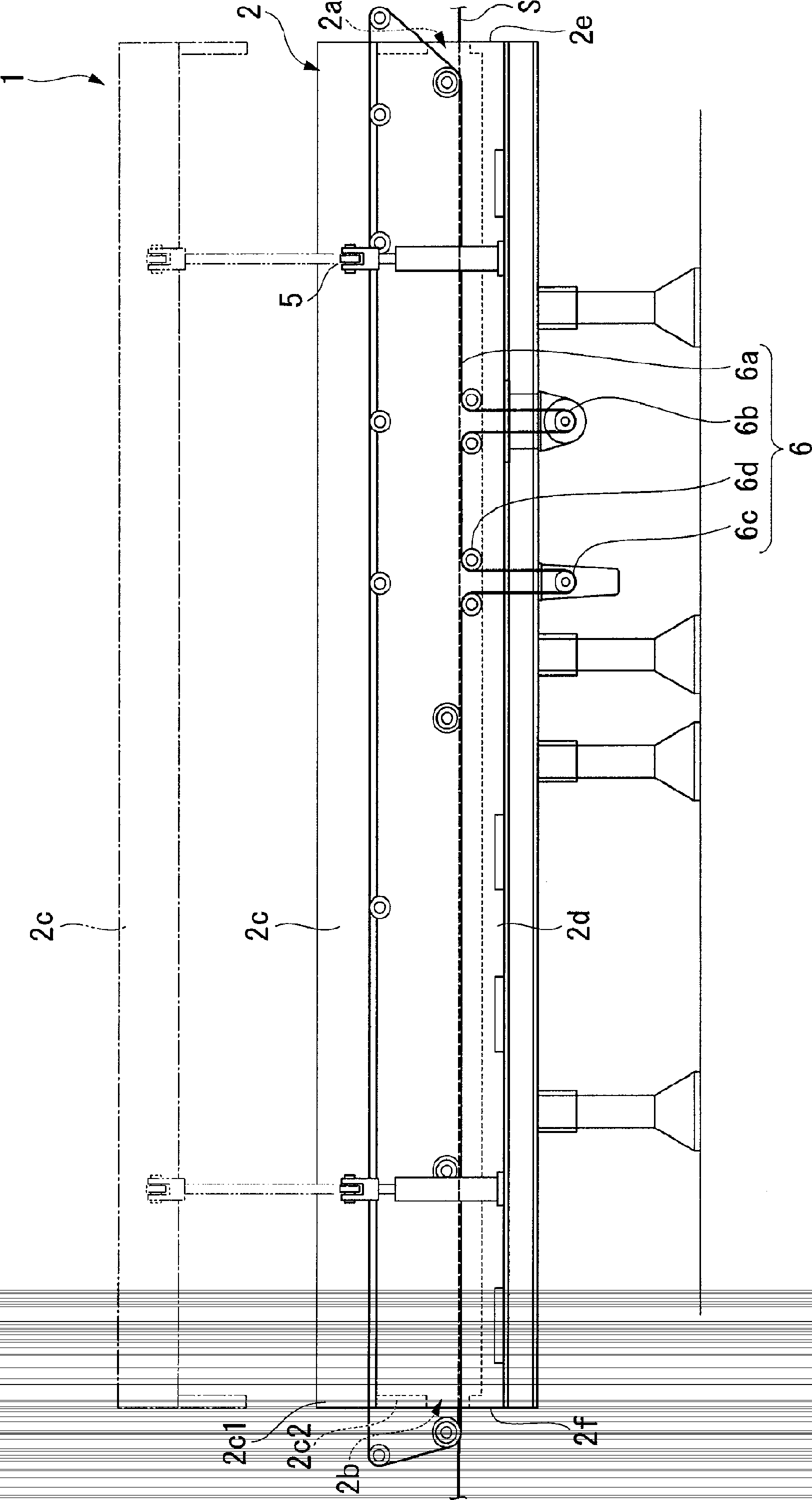
[0027] figure 1 as well as figure 2 is a schematic configuration diagram of the annealing apparatus 1 of the present embodiment, figure 1 is a side view of the annealing device 1, figure 2 is a front view of the annealing apparatus 1 .

[0028] As shown in these figures, the annealing apparatus 1 of this embodiment has the furnace body 2, the conveyance roll 3, the heater 4, the elevating device 5, and the conveyance device 6.

[0029] The sheet S is inserted into the interior of the furnace body 2 through the inlet opening 2a and the outlet opening 2b, and the sheet S is annealed therein. The furnace body 2 has a box shape extending along the conveying direction of the sheet S. As shown in FIG.

[0030] More...


PUM


Abstract

Disclosed is an annealing apparatus which is provided with: a furnace body (2) having a cover part (2c) which makes it possible to expose the inside of the furnace body (2) and which also makes it possible to open an inlet opening (2a) and an outlet opening; and a conveyance device (6) which is disposed outside the furnace body (2) and conveys a sheet (S) by gripping part of said sheet (S). By means of this, the conveyance device is prevented from being exposed to a high-temperature environment, so the lifespan of the conveyance device can be increased.

Description

technical field [0001] The present invention relates to an annealing device that heats and anneals a sheet inserted into a furnace through an inlet opening and an outlet opening of the furnace. [0002] this application claims priority based on Japanese Patent Application No. 2009-032909 for which it applied to Japan on February 16, 2009, and uses the content here. Background technique [0003] Conventionally, an annealing apparatus for annealing to remove internal strain of a sheet is used in a manufacturing apparatus or the like that manufactures a sheet using a rolling process (see Patent Documents 1 to 4). [0004] In the above-mentioned annealing apparatus, the sheets inserted into the furnace body through the inlet opening and the outlet opening of the furnace body are heated and annealed, so that continuously supplied sheets can be processed continuously. [0005] In addition, the annealing apparatus as described above is configured such that a part of the furnace bo...

Claims


Application Information

Patent Timeline
Patent Type & Authority Patents(China)
IPC IPC(8): C21D9/00F27B9/28F27B9/24F27D7/06
CPCF27D1/1808F27B9/243F27B9/24F27B9/28F27D7/06
Inventor 前田宏知根上直行
Owner IHI CORP
Learn More