
Structure for reducing flashover length of moulded case circuit breaker

A molded case circuit breaker and arcing technology, applied in circuit breaker parts and other directions, can solve the problems of large arcing distance, arc short circuit, easy accident, etc., to improve safety performance, reduce arcing distance, and lengthen arc. The effect of moving distance

Active Publication Date: 2012-01-11
BEIJING JINGREN ELECTRICAL CO LTD
View PDF8 Cites 2 Cited by
  • Summary
  • Abstract
  • Description
  • Claims
  • Application Information

AI Technical Summary

Problems solved by technology

[0003] In the existing technology, such as Image 6 As shown: when the arc is sprayed, the upper end of the arc spacer 3 is bent and deformed, and the arc is directly sprayed out to the outside of the circuit breaker along the curved gap of the arc spacer 3. The electric machine must leave enough space in the arcing direction to ensure the normal operation of the circuit breaker, otherwise it will cause arc short circuit

Method used


Image

  • Structure for reducing flashover length of moulded case circuit breaker
  • Structure for reducing flashover length of moulded case circuit breaker
  • Structure for reducing flashover length of moulded case circuit breaker

Examples


Embodiment 1

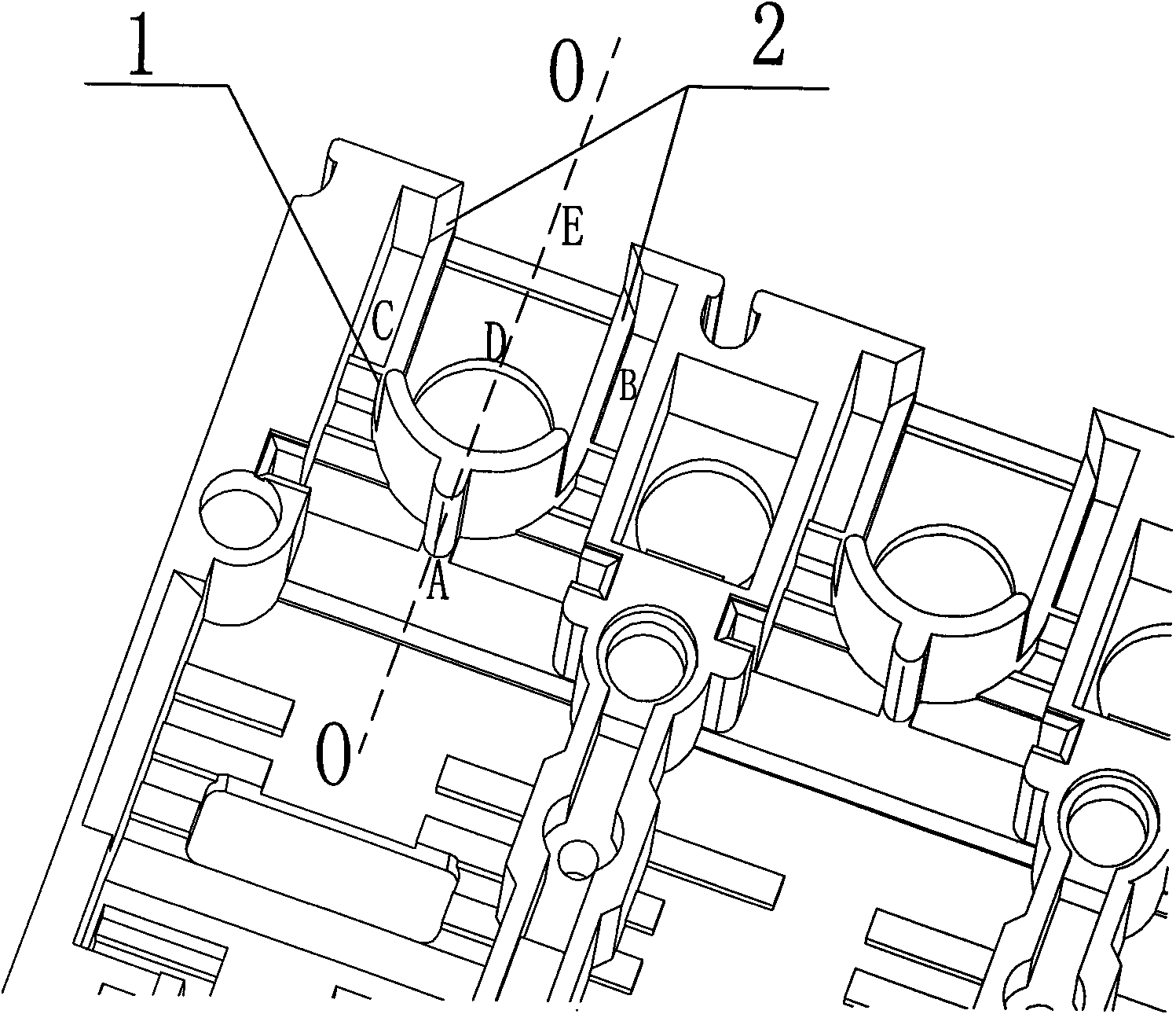
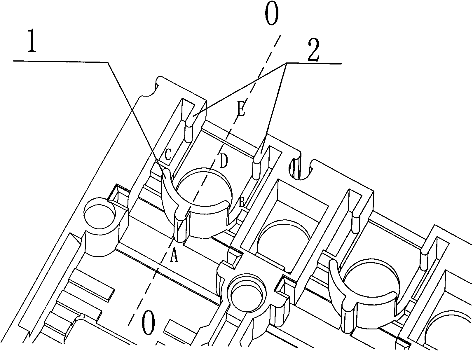
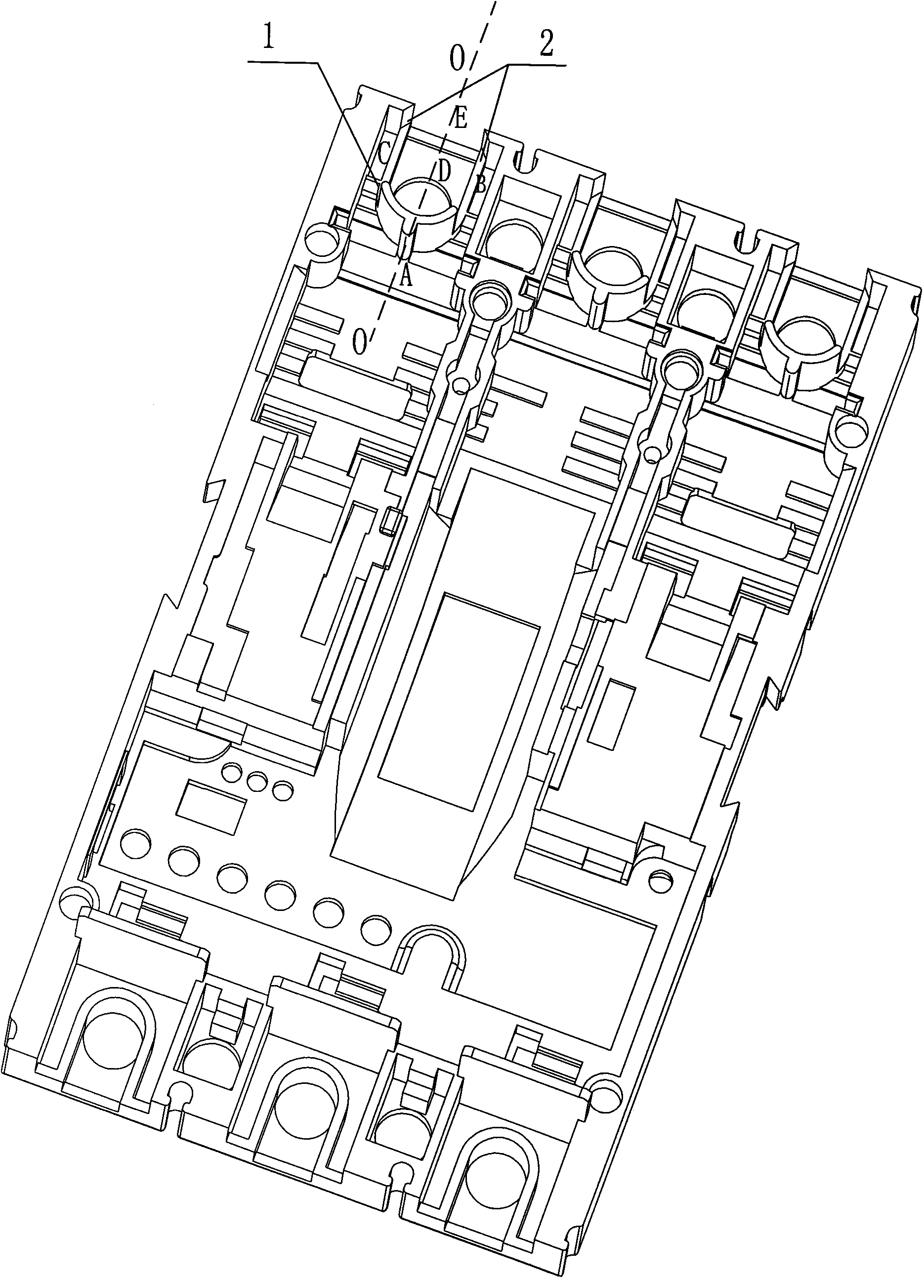
[0030] Such as figure 1 As shown, the large cover of the circuit breaker is provided with an arc-guiding wall structure 1 and an arc-retaining wall structure 2, and at least one of the arc-guiding wall structure and the arc-retaining wall structure corresponds to each electrode of the circuit breaker that needs arc protection.

[0031] The arc-guiding wall 1 is in the shape of an arc, and its arc top faces the direction of the electrode generating the arc. Two arc retaining walls 2 are located in front of both ends of the arc guiding wall 1 .

[0032] The arc retaining wall 2 is an inverted L-shaped wall structure extending forward from the sides of the arc guiding wall and folding inward at the end.

[0033] The inner and outer diameters of the arc guide wall 1 are determined according to the actual needs and the size of the internal structure. The arc retaining wall 2 is facing the O-O axis direction, and the projection of the arc guide wall 1 on a plane perpendicular to t...

Embodiment 2

[0037] Such as figure 2 As shown, the difference between Embodiment 2 and Embodiment 1 is that the arc retaining wall 2 is an inverted U-shaped groove wall that extends forward from the side of the arc guide wall and folds inward at the end and then turns back for a section. body structure.

[0038] When the circuit breaks down and the circuit breaker breaks the problem circuit, a high-energy arc will be generated between the dynamic and static contacts, and the particles with high energy generated during the arc combustion process will be discharged outward. After the arc enters the large cover through the arc extinguishing chamber, it first touches the "arm on the A side of the arc guide wall" at point "A", and after the collision speed slows down, it is divided into two strands towards points "B" and "C". Arc, the arc passes through the "arc blocking wall" to change the direction of the arc, and the hedging collision gathers at the "D" point. At this time, a part of the a...


PUM


Abstract

The invention discloses a structure for reducing flashover length of a moulded case circuit breaker. The structure comprises a big cover and is characterized in that a flashover guiding wall and flashover blocking walls are arranged on the big cover, wherein the front face of the flashover guiding wall faces towards the direction of an electrode generating electric arcs; and the two flashover blocking walls are located in front of the two ends of the flashover guiding wall. The structure of the flashover guiding wall and the structure of the flashover blocking walls change the heading direction of the electric arcs a plurality of times so as to lengthen the moving distance of the electric arcs, meanwhile, the electric arcs collides multiple times so that the electric arcs are weakened to certain extent, and thus, the flashover distance of the circuit breaker is greatly reduced, and the safety performance of the circuit breaker is increased. The structure disclosed by the invention has the characteristics of simple and reliable structure and low cost, and is particularly suitable to being mounted in a small-space and multi-loop control devices.

Description

technical field [0001] The invention relates to a structure for reducing the flashover length of a molded case circuit breaker, which belongs to the field of low-voltage electrical appliances. Background technique [0002] In order to adapt to the continuous increase of grid capacity and the increasingly complex low-voltage power distribution and control system, high-performance and miniaturization requirements are put forward for low-voltage switchgear, that is, while improving the main technical performance, focus on improving comprehensive technical and economic indicators. For example, while improving the short-circuit breaking capacity, special attention should be paid to reducing the length of flashover or achieving "no flashover". [0003] In the existing technology, such as Image 6 As shown: when the arc is sprayed, the upper end of the arc spacer 3 is bent and deformed, and the arc is directly sprayed out to the outside of the circuit breaker along the curved gap o...

Claims


Application Information

Patent Timeline
IPC IPC(8): H01H73/18
Inventor 南寅王洪刚朱金保齐坤
Owner BEIJING JINGREN ELECTRICAL CO LTD
Learn More