
Method for improving viewing angle of liquid crystal display and liquid crystal display

A liquid crystal display, angle technology, applied in the manufacture of instruments, discharge tubes/lamps, optics, etc., can solve problems such as poor film stability, reduce the defect rate of the pair, improve the tolerance error of the pair, and reduce the width. Effect

Inactive Publication Date: 2012-01-11
TCL CHINA STAR OPTOELECTRONICS TECH CO LTD
View PDF5 Cites 17 Cited by
  • Summary
  • Abstract
  • Description
  • Claims
  • Application Information

AI Technical Summary

Problems solved by technology

Although this method can improve the aperture ratio, it needs to add a black light-shielding layer on the 1 / 4 wavelength retardation plate
Especially in the current market, the thin-film type 1 / 4 wavelength retardation film provided by many manufacturers is to directly make a quarter retardation film on the film material. If a black light-shielding layer is added, an additional alignment Exposure, and the steps of developing on the film, easily lead to poor stability of film thickness

Method used


Image

  • Method for improving viewing angle of liquid crystal display and liquid crystal display
  • Method for improving viewing angle of liquid crystal display and liquid crystal display
  • Method for improving viewing angle of liquid crystal display and liquid crystal display

Examples


Embodiment Construction

[0026] It should be understood that the specific embodiments described here are only used to explain the present invention, and are not intended to limit the present invention.

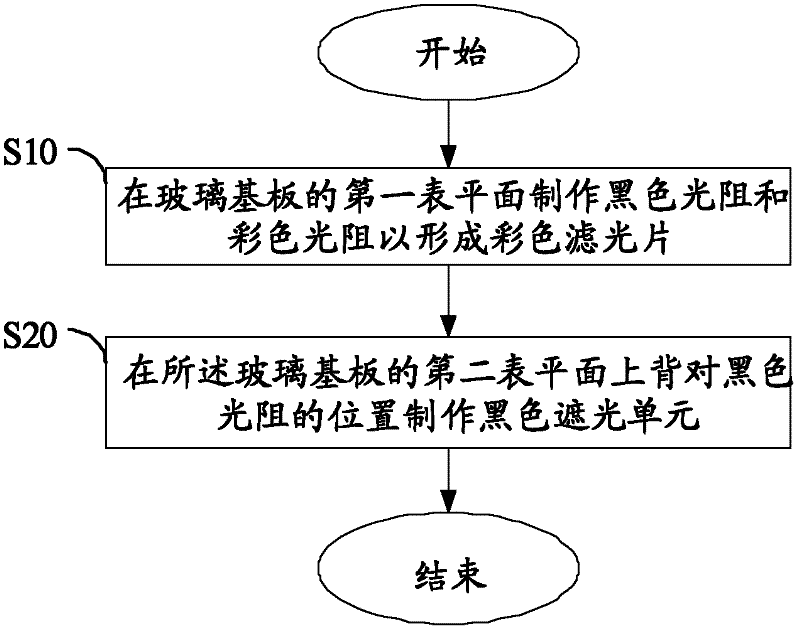
[0027] refer to figure 1 , figure 1 It is a flow chart of a preferred embodiment of the method for improving the viewing angle of a liquid crystal display in the present invention.

[0028] In this embodiment, the method for improving the viewing angle of a liquid crystal display includes the following steps:

[0029] Step S10, fabricating black photoresist and color photoresist on the first surface plane of the glass substrate to form a color filter; in this embodiment, the liquid crystal display (that is, a 3D patterned phase retardation liquid crystal display) includes a color filter, The color filter is composed of a glass substrate, a black photoresist and a color photoresist. The black photoresist and the color photoresist are covered on a surface plane of the glass substrate. The surface pla...


PUM

PropertyMeasurementUnit
widthaaaaaaaaaa

Abstract

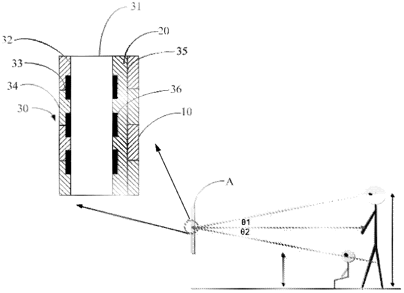
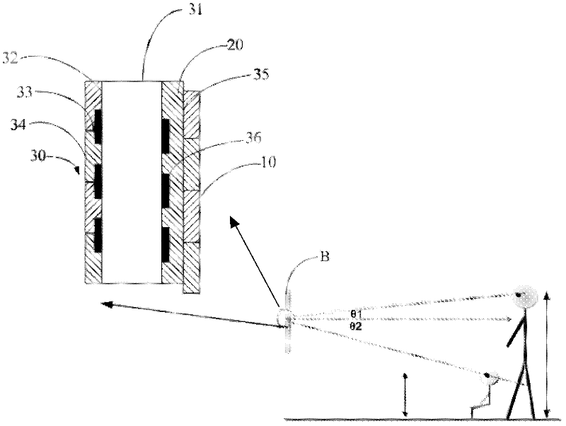
The invention provides a method for improving the viewing angle of a liquid crystal display and a liquid crystal display. The method comprises the steps that: a black shading unit is manufactured at a position on a second surface plane of a glass substrate which is opposite to a black light resistor; and a second surface plane is over against a first surface plane, and the black light resistor and the black shading unit are respectively arranged on both sides of the glass substrate. The method for improving the viewing angle of the liquid crystal display or the liquid crystal display can improve the viewing angle of the liquid crystal display, and increase the aperture opening rate; and in addition, the invention can also improve the pair-group tolerance error of a one-fourth phase difference plate and the liquid crystal display, so that the pair-group defective rate is reduced.

Description

technical field [0001] The invention relates to the field of liquid crystal displays, in particular to a method for improving the viewing angle of a liquid crystal display and a liquid crystal display. Background technique [0002] As we all know, in a 3D liquid crystal display, the light emitted by the polarizer on the color filter side of the liquid crystal display is linearly polarized light. Vertical linearly polarized light. After the two linearly polarized lights pass through the 1 / 4 wavelength retardation plate with an included angle of 45 degrees, they will form left-handed circularly polarized light and right-handed circularly polarized light. Left-handed circularly polarized light and right-handed circularly polarized light pass through the 1 / 4 wavelength retardation plate on the glasses to form linearly polarized light, and then pass through the polarizer on the glasses to reach the left and right eyes respectively. A piece of glass and a polarizer (total thickn...

Claims


Application Information

Patent Timeline
Patent Type & Authority Applications(China)
IPC IPC(8): G02F1/1335G02B30/30
CPCG02F2001/133638H01J9/00G02B27/2214G02F2001/133631G02F1/133512G02F1/1333G02F1/133631G02F1/133638G02B30/30G02B30/27
Inventor 萧嘉强陈峙彣贺成明
Owner TCL CHINA STAR OPTOELECTRONICS TECH CO LTD
Learn More