
Automatic tube insertion chain of plastic bottle tube heater

A heater and plastic bottle technology, applied in the field of plastic machinery, can solve the problems of high power consumption, high production cost, unstable operation, etc.

Active Publication Date: 2012-01-11
林明茳
View PDF5 Cites 2 Cited by
  • Summary
  • Abstract
  • Description
  • Claims
  • Application Information

AI Technical Summary

Problems solved by technology

[0002] The heater of the existing plastic bottle blowing machine, the support seat used for inserting the bottle tube in the bottle tube conveying mechanism is installed on the side of the conveying chain. , self-rotating gears, etc., especially the hanging plate, the upper and lower connecting fixed blocks are troublesome to process, large in size, heavy in weight, and high in production costs; at the same time, the width of the heater is increased by the bottle tube conveying mechanism installed in the side. As a result, the whole machine occupies a large space, and the conveying mechanism with a large width requires double rows of heating lamps, which consumes a lot of power and is troublesome to debug; and the support seat is installed on one side of the conveying chain, so the operation is unstable and the service life of the chain is shortened

Method used


Image

  • Automatic tube insertion chain of plastic bottle tube heater
  • Automatic tube insertion chain of plastic bottle tube heater
  • Automatic tube insertion chain of plastic bottle tube heater

Examples


Embodiment Construction

[0014] Embodiments of the present invention will be further described below in conjunction with the accompanying drawings.

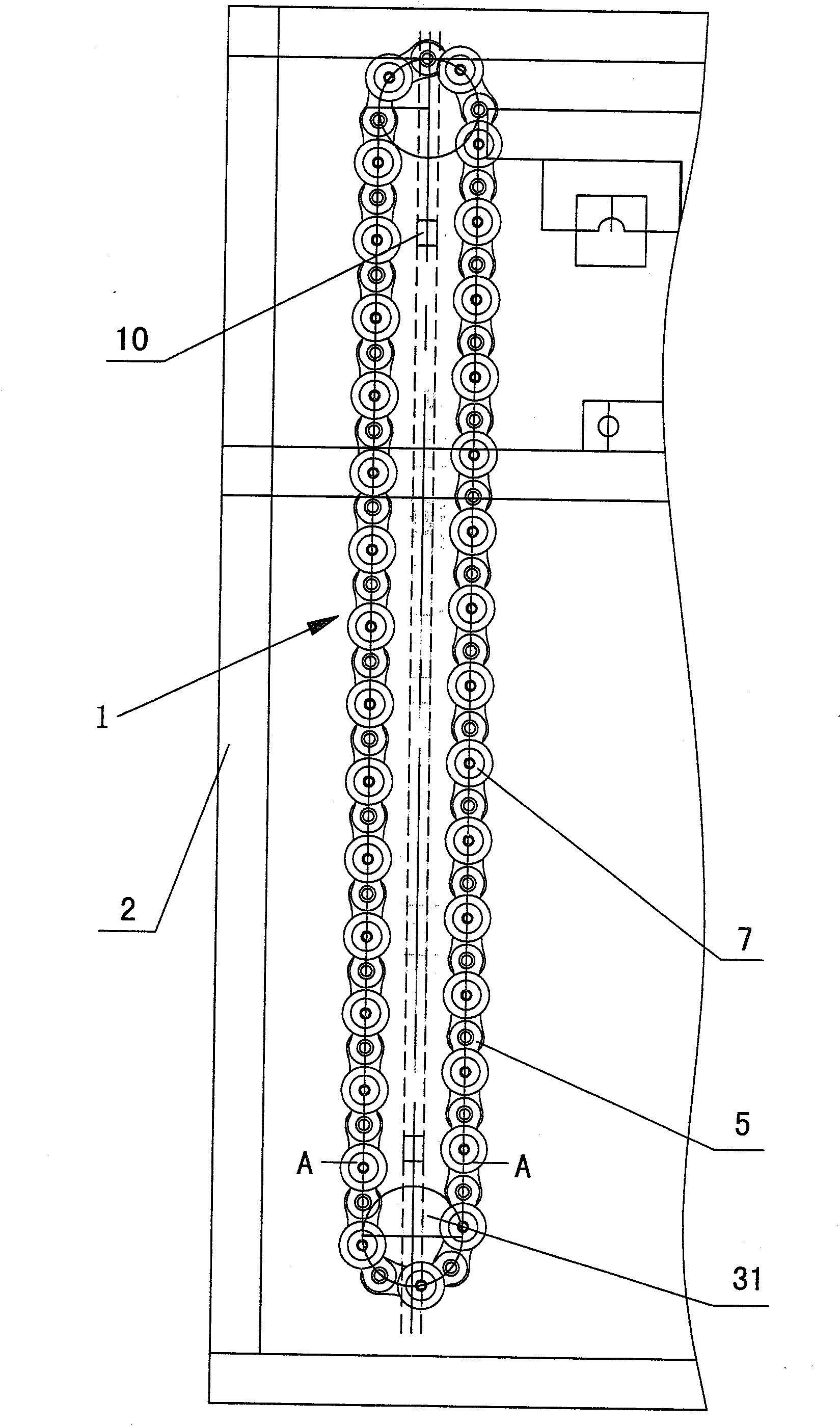
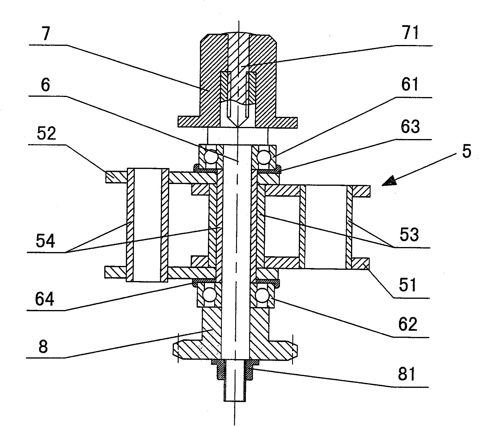
[0015] like Figure 1-Figure 6 As shown, the intubation chain of the plastic bottle tube heater itself includes a frame 2, and a bottle tube conveying mechanism 1 is installed on the frame. Drive the driven sprocket through the conveying chain 5, and the conveying chain 5 drives the bottle tube support seat. The conveying chain 5 includes an inner chain piece 51 and an outer chain piece 52, and the inner chain piece 51 and the outer chain piece are connected by chain pins. The chain pins described include long pipe chain pins 54 and short pipe chain pins 53. The two ends of the long pipe chain pins 54 are respectively fixed with the outer chain sheet 52. The short pipe chain pins 53 are sleeved outside the long pipe chain pins 54. The inner chain piece 51 is fixed, and it is characterized in that the bottle tube support shaft 6 is installed inside the l...


PUM


Abstract

The invention relates to an automatic tube insertion chain of a plastic bottle tube heater. The automatic tube insertion chain comprises a frame; a bottle tube conveying mechanism is arranged on the frame; the bottle tube conveying mechanism drives a rotating shaft by power; a driving chain wheel is arranged on the rotating shaft; the driving chain wheel drives a driven chain wheel through a conveying chain; the conveying chain drives a bottle tube supporting seat; the conveying chain comprises an inner chain sheet and an outer chain sheet, and the inner chain sheet is connected with the outer chain sheet by a chain pin; and the chain pin comprises a long tube chain pin and a short tube chain pin, two ends of the long tube chain pin are respectively fixed with the outer chain sheet, the short tube chain pin is sleeved outside the long tube chain pin, and two ends of the short tube chain pin are respectively fixed with the inner chain sheet. The automatic tube insertion chain is characterized in that: a bottle tube supporting shaft is arranged in the long tube chain pin, an upper bearing and a lower bearing are arranged outside the bottle tube supporting shaft, an upper bearing washer is arranged between the upper bearing and the outer chain sheet, a lower bearing washer is arranged between the lower bearing and the outer chain sheet, a bottle tube supporting plug is arranged at the upper end of the bottle tube supporting shaft, and an autorotation gear is arranged at the lower end of the bottle tube supporting shaft.

Description

technical field [0001] The invention relates to a self-insertion pipe chain of a plastic bottle pipe heater, which belongs to the technical field of plastic machinery. Background technique [0002] The heater of the existing plastic bottle blowing machine, the support seat used for inserting the bottle tube in the bottle tube conveying mechanism is installed on the side of the conveying chain. , self-rotating gears, etc., especially the hanging plate, the upper and lower connecting fixed blocks are troublesome to process, large in size, heavy in weight, and high in production costs; at the same time, the width of the heater is increased by the bottle tube conveying mechanism installed in the side. As a result, the whole machine occupies a large space, and the conveying mechanism with a large width requires double rows of heating lamps, which consumes a lot of power and is troublesome to debug; and the support seat is installed on one side of the conveying chain, so the opera...

Claims


Application Information

Patent Timeline
Patent Type & Authority Applications(China)
IPC IPC(8): B29C49/42B29C49/64B29C31/08B29L22/00
Inventor 林明茳
Owner 林明茳
Learn More