Structure of modular robot actuation system

A technology of drive unit and module structure, applied in manipulators, program-controlled manipulators, manufacturing tools, etc., can solve problems such as hindering robot movements, unsightly appearance, mechanical loss, etc., and achieve the effect of flexible movements

Active Publication Date: 2012-01-04
KOREA INST OF MACHINERY & MATERIALS
View PDF5 Cites 2 Cited by
  • Summary
  • Abstract
  • Description
  • Claims
  • Application Information

AI Technical Summary

Problems solved by technology

At this time, the extra cable 9 has sufficient length to prevent the output connector 3b of the first module fixing part 3 or the input connector 5a of the second module fixing part 5 from coming off due to the rotation of the first module rotating part 4 , so it is not very elegant, and because the cable twists and interferes with other modules, it becomes a factor that hinders the movement of the robot, and even causes mechanical loss

Method used


Image

  • Structure of modular robot actuation system
  • Structure of modular robot actuation system
  • Structure of modular robot actuation system

Examples


Embodiment Construction

[0024] Hereinafter, preferred embodiments of the present invention will be described in further detail with reference to the accompanying drawings. When labeling the components in the drawings, the same reference signs are used as much as possible for the same components in different drawings. When describing the present invention, the detailed descriptions of related known functions or structures that may cause unnecessary confusion to the gist of the present invention are omitted. In addition, based on the principle that the inventor can properly define the terms and concepts in order to best describe his invention, the terms or words used in this specification and claims can only be used in accordance with the meaning and meaning of the technical idea of ​​the present invention. concept explained.

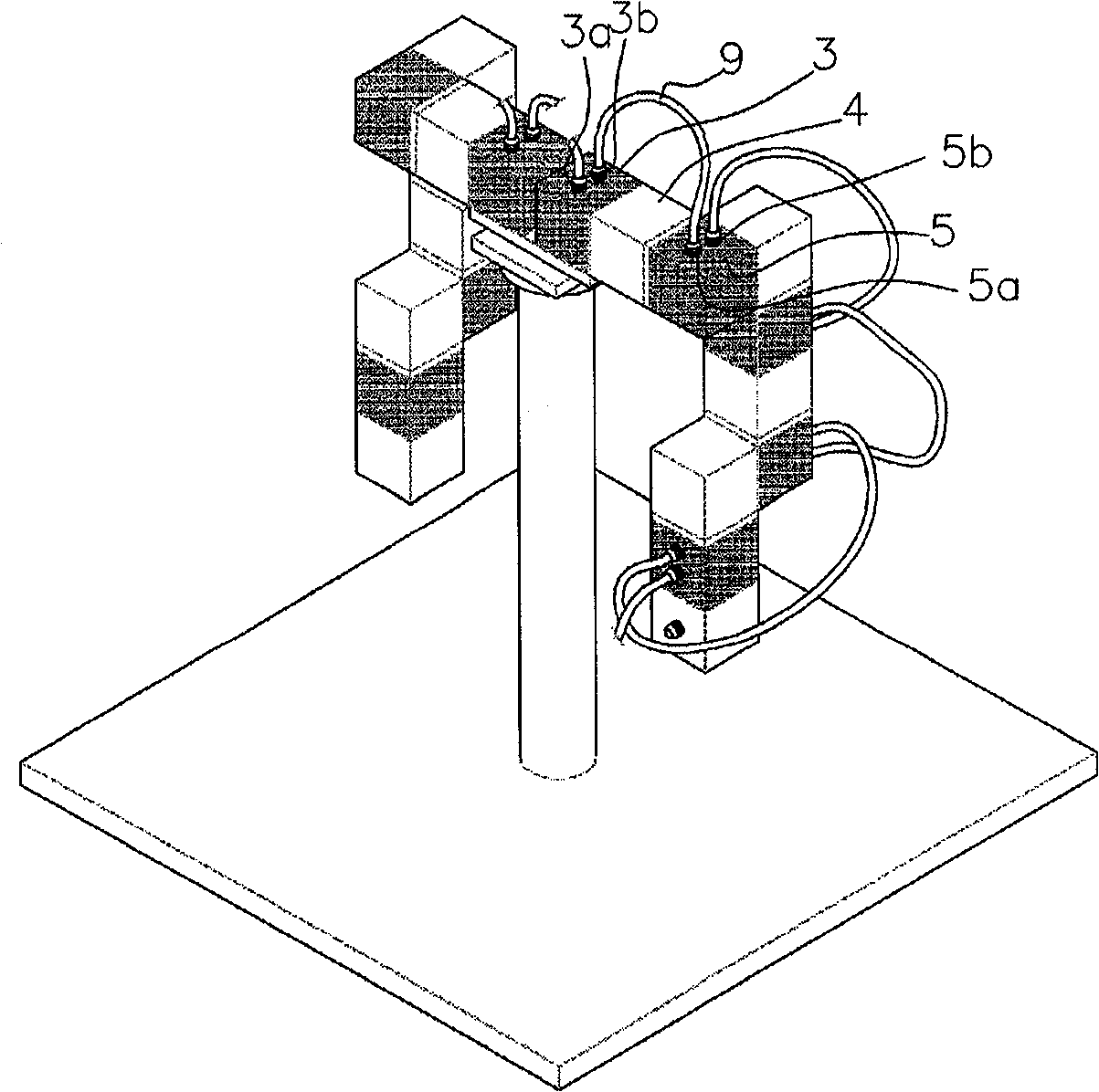
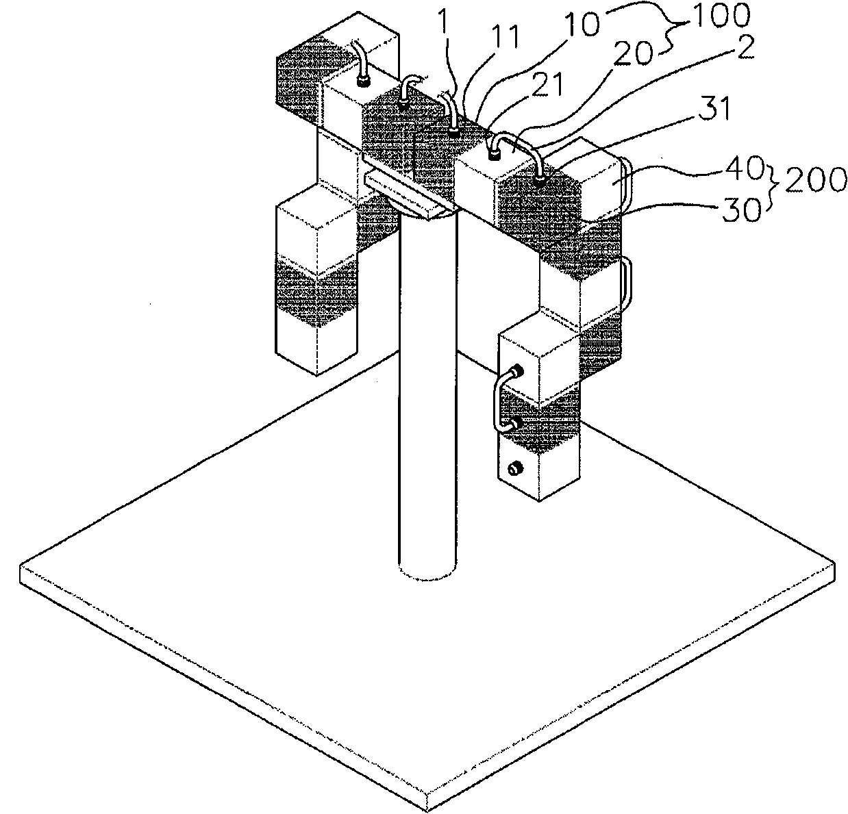
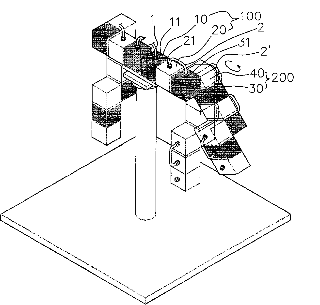
[0025] The invention relates to a module structure of a robot with more than two degrees of freedom. An input connector 11 and an output connector 21 to which cables 1 and 2 a...


PUM


Abstract

The present invention relates to a structure of a module of a robot having at least two degrees of freedom (2DOF). More particularly, the present invention relates to a structure of a modular robot actuation system, comprising: a fixed housing forming the outer appearance of the module; a rotatable housing connected to the fixed housing; and an input connector and an output connector with respective cables connected to the outside of the fixed housing and to the outside of the rotatable housing, respectively. The input connector and the output connector are interconnected through the inside of the fixed housing and the inside of the rotatable housing. The cable connected to the output connector of the rotatable housing is connected to the input connector of the fixed housing forming the outer appearance of another module, which is identical to the above-described module and also has a rotatable housing.

Description

technical field [0001] The present invention relates to a modular structure possessed by a robot with at least two degrees of freedom (2DOF: 2 Degrees of Freedom), and more specifically relates to a modular robot drive unit structure, in which the fixed shell and the The outer side of the rotating housing connected to the fixed housing for rotation is respectively provided with an input connector and an output connector for connecting cables, and the input connector and the output connector are connected to the inside of the rotating housing through the fixed housing, and The cable connected to the output connector of the rotating housing is then connected to the input connector of the fixed housing and the rotating housing that constitute another module having the same appearance as the module. Background technique [0002] General educational or research module structures with more than two degrees of freedom, such as figure 1 As shown, it is roughly divided into a fixed ...

Claims


Application Information

Patent Timeline
Patent Type & Authority Applications(China)
IPC IPC(8): B25J9/08B25J19/00
CPCB25J19/0029B25J9/08
Inventor 朴灿勋景珍晧朴东日
Owner KOREA INST OF MACHINERY & MATERIALS
Why Eureka
Try Eureka