
Aerated switch cabinet

A technology of inflatable cabinets and switchgears, which is applied in the direction of switchgear, switchgear settings, electrical components, etc., which can solve the problems of large volume, many mechanical components, and poor reliability of permanent magnet vacuum switches, so as to reduce maintenance and repair time during power outages, The effect of compact structure and high reliability

Inactive Publication Date: 2012-01-04
武汉百楚科技有限公司
View PDF4 Cites 3 Cited by
  • Summary
  • Abstract
  • Description
  • Claims
  • Application Information

AI Technical Summary

Problems solved by technology

[0003] (1) The conventional switchgear adopts a spring operating mechanism, with many mechanical components and complex structure, and mechanical locks are required when opening and closing. These mechanical parts are subjected to mechanical impact during each opening and closing operation, which is a traditional The main reason for the mechanical failure of the circuit breaker is poor reliability, and the mechanical characteristics of the spring operating mechanism are not well matched with the breaking characteristics of the vacuum switch; in addition, because the spring operating mechanism does not support the intelligence of the switch cabinet, it does not meet the requirements of the smart grid. requirements
[0004] (2) All primary components in conventional switchgear such as circuit breakers, isolating switches, busbars, etc. are air-insulated, so the requirements for the operating environment are relatively high, and generally cannot be used under harsh conditions
[0005] In addition, the space in the switch cabinet is extremely limited, and a certain insulation distance must be met under high-voltage conditions to ensure the safe use of various components
Due to the large size of the conventional permanent magnet vacuum switch, it cannot be applied in the switchgear, especially it cannot meet the requirements of the current smart grid for the primary equipment and the development direction of the primary equipment.

Method used


Image

  • Aerated switch cabinet
  • Aerated switch cabinet
  • Aerated switch cabinet

Examples


Embodiment Construction

[0015] The technical solution of the present invention will be further described below in conjunction with the accompanying drawings and specific embodiments.

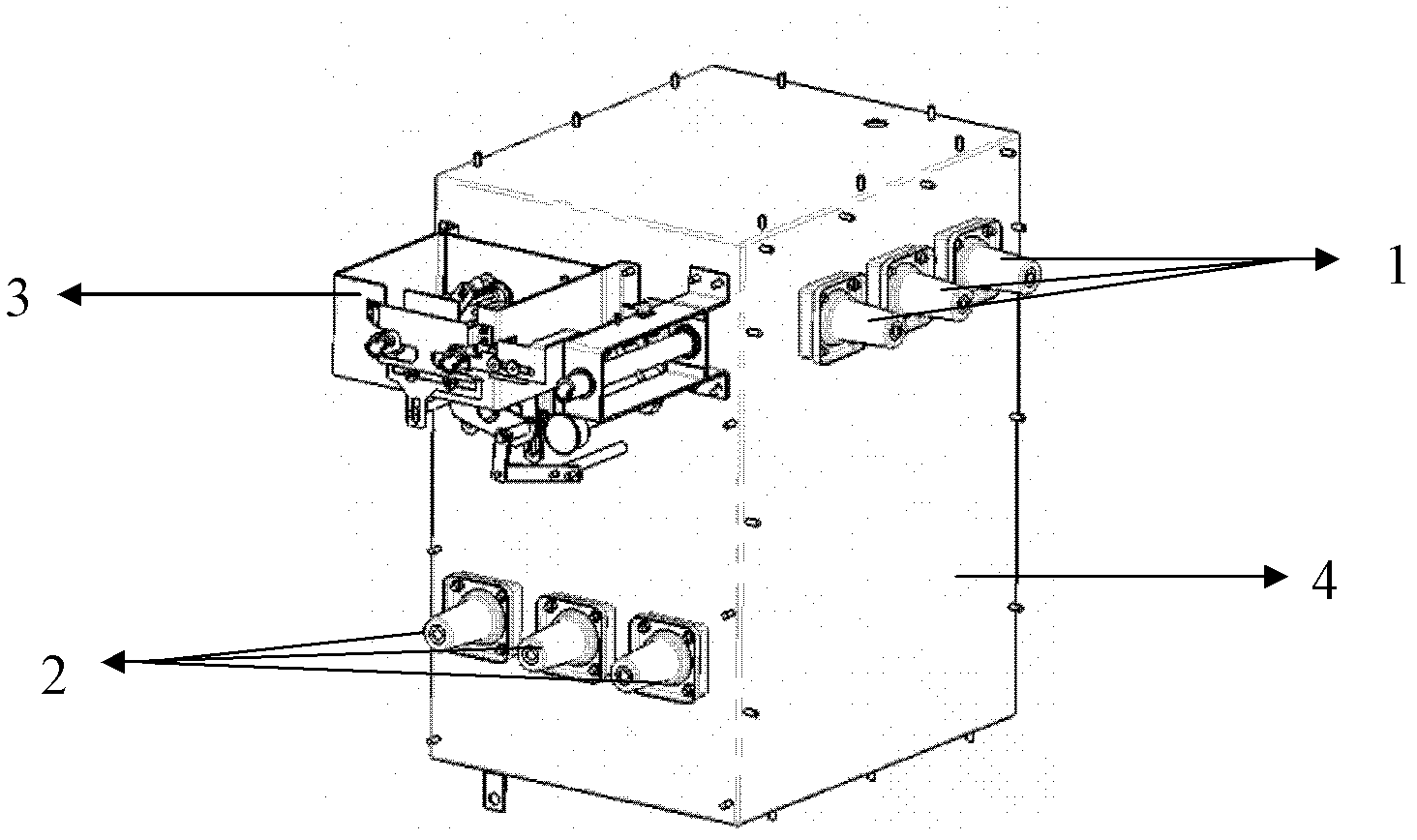
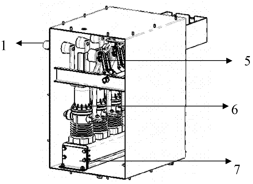
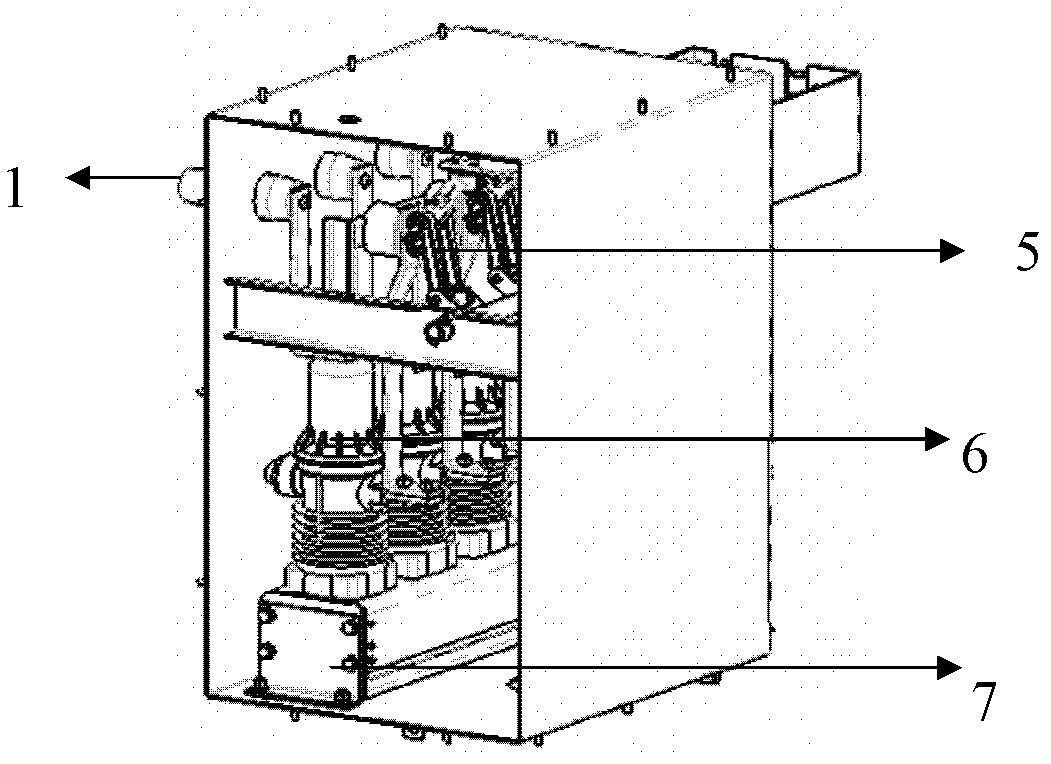
[0016] A switchgear, at least including gas-filled cabinets and high-voltage components, the external structure of which is as follows figure 1 As shown, it includes a casing 4, and the casing 4 is provided with an incoming wire end 1, an outgoing wire end 2 and a locking mechanism. The internal structure of the inflatable switchgear is as follows: figure 2 As shown, it includes: a permanent magnet vacuum switch 6 and an isolation-grounding three-position switch 5. The permanent magnet vacuum switch 6 and the isolation-grounding three-position switch 5 are integrally connected and sealed in an inflatable cabinet. The high-voltage components are also sealed in the air-filled cabinet. The inflatable cabinet is a fully sealed structure made of stainless steel.

[0017] The traditional operating mechanism uses an extre...


PUM


Abstract

The invention discloses an aerated switch cabinet, at least comprising an aerated cabinet, a high-voltage component, a permanent-magnetic vacuum switch and a isolating-grounding three-position switch, wherein the permanent-magnetic vacuum switch and the isolating-grounding three-position switch are connected integrally and arranged in the aerated cabinet in a closed mode. In the aerated switch cabinet, the permanent-magnetic vacuum switch and the integral design are used, thus realizing the good safety, the high reliability, the strong adaptability and the maintenance-free effect. The aerated switch cabinet is applied to 10-35kV power distribution networks with ungrounded neutral points, neutral points grounded by arc suppression coils and neutral points grounded by resistance.

Description

technical field [0001] The invention relates to an electrical device, in particular to an inflatable switchgear in a power distribution network. Background technique [0002] The switchgear is a large number of equipment used in the distribution network, and the safety of the switchgear is directly related to the safety and power supply reliability of the distribution network. Conventional switchgear adopts spring operating mechanism. Generally, all primary components such as circuit breakers, disconnectors, busbars, etc. are insulated by air, and only some switchgears are fully enclosed in gas-filled cabinets. Therefore, the conventional switchgear mainly has the following problems: [0003] (1) The conventional switchgear adopts a spring operating mechanism, with many mechanical components and complex structure, and mechanical locks are required when opening and closing. These mechanical parts are subjected to mechanical impact during each opening and closing operation, w...

Claims


Application Information

Patent Timeline
IPC IPC(8): H02B13/035H02B13/025
Inventor 陈俊武
Owner 武汉百楚科技有限公司
Learn More