
F-track movable end positioning and connection device for medium-and-low-speed magnetic suspension turnout

A connecting device and movable end technology, which is applied in the field of positioning and connecting devices for F rail movable ends of medium and low-speed maglev turnouts, can solve the problems of uncontrollable positioning in the left and right directions, head shaking of the device movement, etc., achieves convenient installation and adjustment, and prevents left and right shaking and vertical jumping , The effect of high positioning accuracy

Active Publication Date: 2012-01-04
CHINA RAILWAY BAOJI BRIDGE GRP +1
View PDF5 Cites 10 Cited by
  • Summary
  • Abstract
  • Description
  • Claims
  • Application Information

AI Technical Summary

Problems solved by technology

The prior art closest to the present invention is the "Vertical Positioning and Connecting Device for the Movable End of the F Rail of Medium and Low Speed ​​Maglev Turnout" which is tried out in the Tangshan Test Line. The fixed support is directly welded on the turnout beam, and the movable support is hinged on the fixed support. As a result, the left and right degrees of freedom of the turnout beam are not restricted at the moment of movement. When the turnout beam is in place, due to the inertia of the movement, the device moves too much and the head shakes, and the positioning of the docking line in the left and right directions cannot be controlled.

Method used


Image

  • F-track movable end positioning and connection device for medium-and-low-speed magnetic suspension turnout
  • F-track movable end positioning and connection device for medium-and-low-speed magnetic suspension turnout
  • F-track movable end positioning and connection device for medium-and-low-speed magnetic suspension turnout

Examples


Embodiment Construction

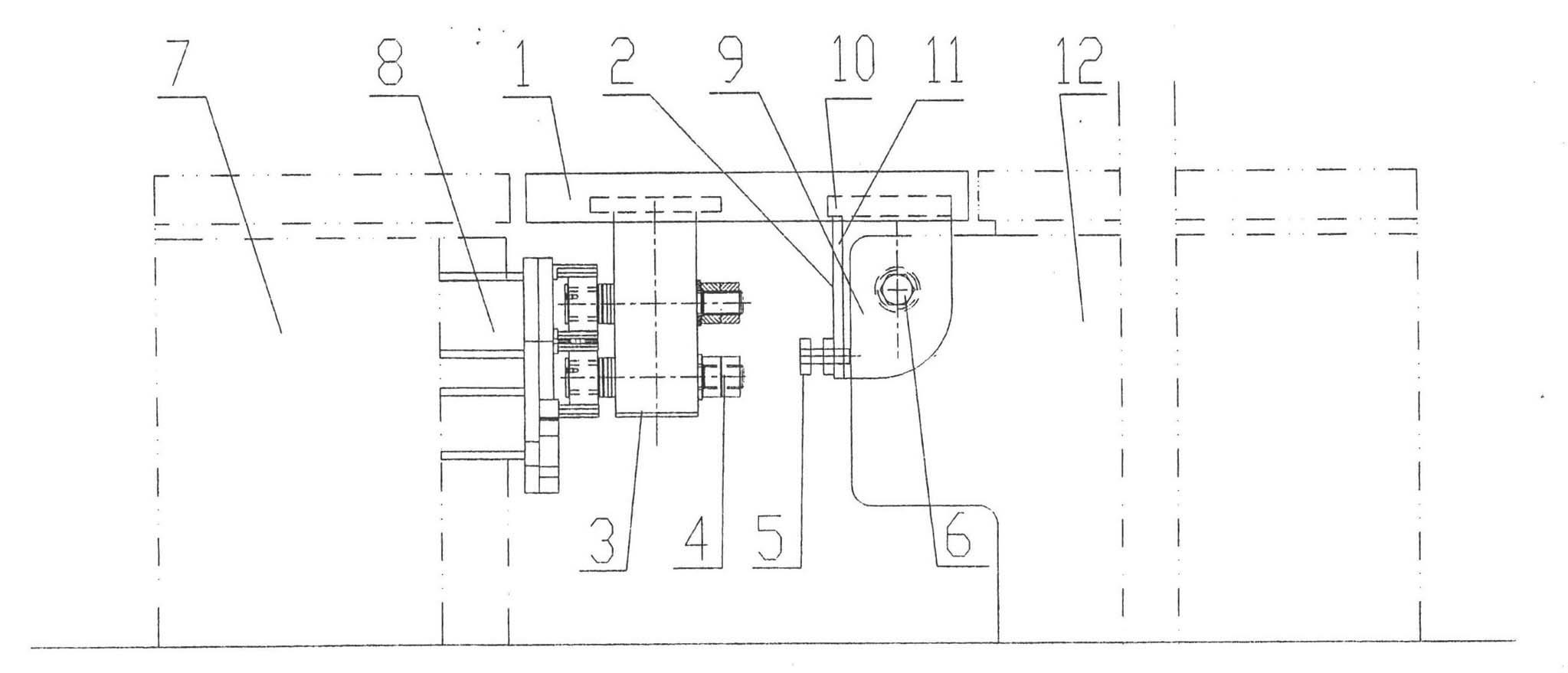
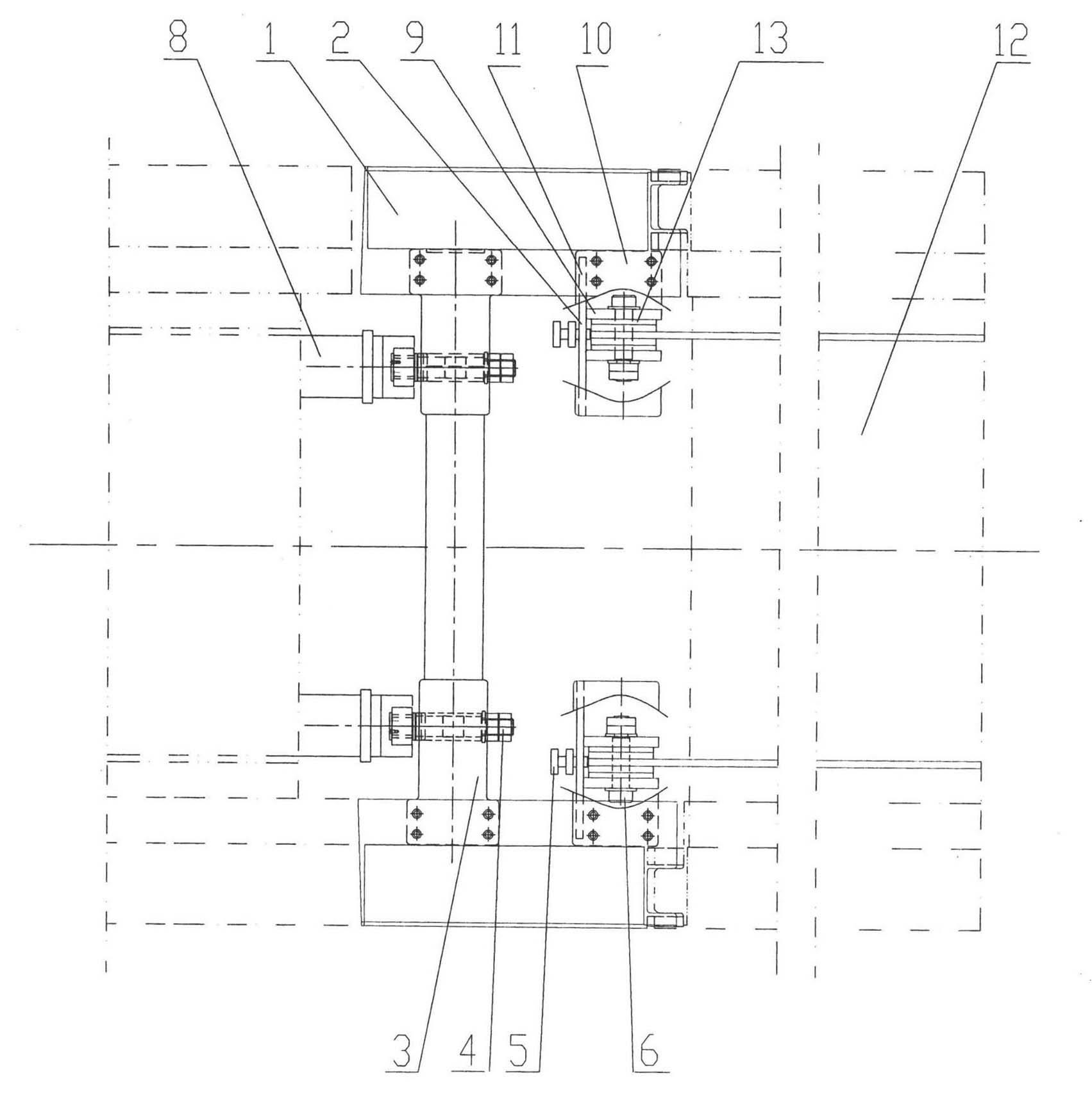
[0011] Attached below figure 1 , 2 An embodiment of the present invention is described.

[0012] A positioning and connecting device for the movable end of the F rail of a medium-low speed maglev turnout, comprising two symmetrical sections of the movable end 1 of the F rail, and the front ends of the movable end 1 of the two symmetrical sections of the F rail are fixed by a connecting beam 3 located below it Connected together, the left and right ends of the connecting beam 3 are respectively equipped with guide wheel assemblies 4, and the two guide wheel assemblies 4 are respectively opposite to the two C-shaped grooves 8 on the inner end surface of the stacking beam 7 . The rear ends of the movable ends 1 of the left and right symmetrical two-section F rails are fixedly connected with a movable hinge seat 2, and the movable hinge seat 2 is composed of a pair of ear plates 9, an upper connecting plate 10, a front side plate 11 and a pin shaft. 6 constitutes; the upper conn...


PUM


Abstract

The invention discloses an F-track movable end positioning and connection device for a medium-and-low-speed magnetic suspension turnout. The F-track movable end positioning and connection device comprises two sections of F-track movable ends which are symmetrical left and right. A movable hinged support is fixedly connected with the lower part of the rear end of each of the two sections of F-track movable ends which are symmetrical left and right; each movable hinged support consists of a pair of ear plates, an upper connection plate, a front side plate and a pin roll; the upper connection plate is fixedly connected with the upper ends of the pair of the ear plates and the lower part of the F-track movable end, and the front side plate is fixedly connected with the front end of the pair of the ear plates and the lower part of the upper connection plate; and the pair of the ear plates are inserted into two sides of an extension end of a turnouttrack web of the turnout and are hinged with two sides of the extension end of the turnouttrack web of the turnout through the pin roll, each front side plate is provided with an adjusting screw and the front end of the adjusting screw is pressed against the extension end of the turnouttrack web of the turnout. The left and right freedom degree of the F-track movable end positioning and connection device is limited on the premise that thevertical freedom degree of the device is limited, and the turnout is prevented from swinging left and right and jumping in a vertical direction.

Description

technical field [0001] The invention belongs to the technical field of turnout design for medium and low-speed maglev transportation systems, and in particular relates to a positioning and connecting device for the movable end of an F rail of a medium-low speed maglev turnout. Background technique [0002] Because of the advantages of safety, comfort, strong climbing ability and low noise, medium and low-speed maglev transportation has broad development prospects as a new urban rail transit mode. The vertical positioning device for the movable end of the F rail of the medium and low speed maglev turnout is an important part of the medium and low speed maglev turnout. It is a device for docking and positioning the F rail on the movable beam of the turnout and the F rail on the fixed beam. The device should be able to move flexibly with the turnout beam, and the vertical degree of freedom should be restricted after moving in place, so that the F rail at the movable end can be ...

Claims


Application Information

Patent Timeline
IPC IPC(8): E01B25/34
Inventor 吉敏廷王永宁王红霞李毅刘炜王孝儒蒋建湘罗坤骆力
Owner CHINA RAILWAY BAOJI BRIDGE GRP
Learn More