A battery and liquid injection method

A battery and liquid injection technology, applied in battery pack parts, circuits, electrical components, etc., can solve the problems of incomplete electrolyte infiltration, difficult discharge of cell bubbles, and reduced battery capacity, achieving good infiltration effect and shortening injection time. The effect of improving liquid time and safety performance

Active Publication Date: 2011-12-28
中创新航科技(江苏)有限公司
View PDF4 Cites 14 Cited by
  • Summary
  • Abstract
  • Description
  • Claims
  • Application Information

AI Technical Summary

Problems solved by technology

Existing batteries with both a safety valve and a liquid injection hole have both the safety valve and the liquid injection hole set on the top of the battery. At present, the electrolyte injection methods used by manufacturers for this battery include negative pressure method, positive pressure method, Positive and negative pressure mixing method, centrifugation method and vibration method, etc. These liquid injection methods are all from the top of the battery to the bottom. In the process of liquid injection, new air bubbles are easy to form, resulting in incomplete penetration of the electrolyte, reduced battery capacity, and slow liquid injection speed.

Method used


Image

  • A battery and liquid injection method
  • A battery and liquid injection method
  • A battery and liquid injection method

Examples


Embodiment 1

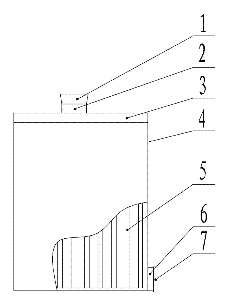
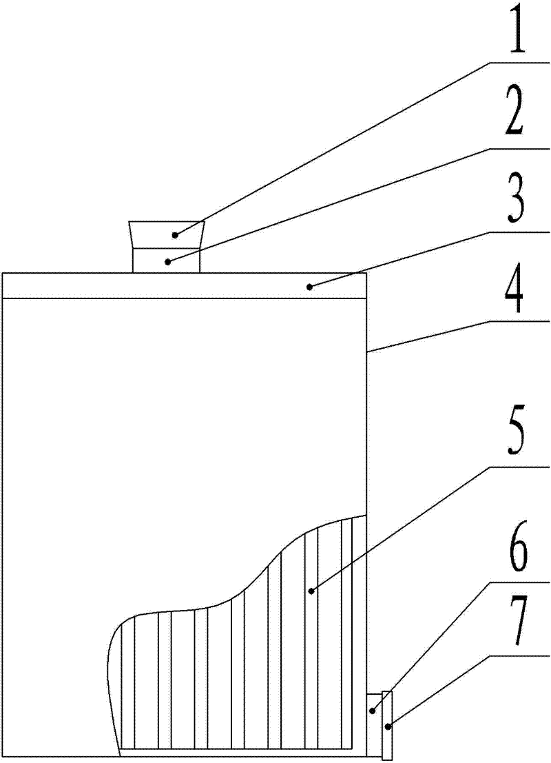
[0022] Such as figure 1 As shown, a battery provided in this embodiment includes a battery winding core 5, a casing 4 wrapped outside the battery winding core 5, and an end cap 3 covering the top of the casing 4, and also includes a safety valve hole 2 and The liquid injection hole 6 and the safety valve hole 2 are arranged on the end cover 3 , and the liquid injection hole 6 is arranged at the lower part of the housing 4 . The safety valve hole 2 is provided with a safety valve cover 1 , and the liquid injection hole 6 is provided with a liquid injection hole cover 7 .

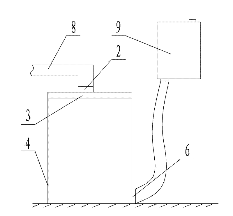
[0023] Such as figure 2 As shown, the battery injection method provided in this embodiment, the specific steps are as follows:

[0024] (1) Place the battery in dry air with a dew point of -50°C, remove the safety valve cover 1, and connect the safety valve hole 2 with the vacuum line 8;

[0025] (2) Remove the liquid injection hole cover 7 of the battery, connect the liquid injection hole 6 with the liqu...


PUM


Abstract

The invention discloses a cell and an electrolyte injection method. The cell comprises a cell rolling core, a shell wrapped outside the cell rolling core, an end cover covering the upper part of the shell, a safety valve hole and an electrolyte injection hole, wherein the safety valve hole is arranged on the end cover, and the electrolyte injection hole is arranged at the lower part of the shell. In the cell, the safety valve hole is arranged on the end cover of the cell, and the electrolyte injection hole is arranged at the lower part of the shell of the cell. When the electrolyte is injected into the cell, the vacuumization is carried out from the safety valve hole, and the electrolyte is injected from the electrolyte injection hole at the bottom of the cell. The electrolyte injection efficiency of the cell is improved obviously, and because the electrolyte injection way that the electrolyte is injected from the bottom of the cell and the vacuumization is carried out at the upper part of the cell is adopted, air bubbles inside the cell are reduced. The infiltration effect of the cell rolling core is good, thus the cell capacity is greatly increased. By using the electrolyte injection method, the electrolyte injection time is shortened effectively, the working efficiency is improved, the infiltration of the cell rolling core is more thorough, the air bubbles between pole pieces can be discharged, and the cell capacity is increased.

Description

technical field [0001] The invention relates to the technical field of batteries, in particular to a battery with a safety valve and a liquid injection hole and a liquid injection method thereof. Background technique [0002] Currently common batteries have various forms, such as completely sealed, with a safety valve, with a liquid injection hole for multiple injections, and with both a safety valve and a liquid injection hole. Existing batteries with both a safety valve and a liquid injection hole have both the safety valve and the liquid injection hole set on the top of the battery. At present, the electrolyte injection methods used by manufacturers for this battery include negative pressure method, positive pressure method, Positive and negative pressure mixing method, centrifugation method and vibration method, etc. These liquid injection methods are all from the top of the battery to the bottom. It is also easy to form new air bubbles during the liquid injection proce...

Claims


Application Information

Patent Timeline
Patent Type & Authority Applications(China)
IPC IPC(8): H01M2/04H01M2/36H01M2/12
CPCY02E60/12Y02E60/10
Inventor 李铁南韩冰海张祥张金梅徐建波程康
Owner 中创新航科技(江苏)有限公司
Why Eureka
Try Eureka