
Two-axis gyroscope with piezo-driven capacitive sensing

A technology of capacitance detection and two-axis gyroscope, which is applied in the field of micro gyroscope, can solve the problems of gyroscope performance influence, stress concentration, and small effective vibration amplitude, etc., and achieve the effect of easy processing technology, strong impact resistance and high reliability

Inactive Publication Date: 2011-12-28
SHANGHAI JIAO TONG UNIV
View PDF4 Cites 28 Cited by
  • Summary
  • Abstract
  • Description
  • Claims
  • Application Information

AI Technical Summary

Problems solved by technology

[0005]This technology has the following disadvantages: First, because there are multiple electrodes on the upper and lower surfaces, the processing technology is complicated, the positioning accuracy of the double-sided electrodes is high, and multiple electrodes The lead wire of the gyroscope will also have an impact on the performance of the gyroscope; secondly, the piezoelectric vibrator is a square piezoelectric block, and its rigidity is relatively large, so the effective vibration amplitude generated is small; thirdly, because the piezoelectric vibrator is a square piezoelectric block, its There is a right-angle edge, which will cause stress concentration during the stress process, and affect the reliability and life of the gyroscope under high-frequency working conditions

Method used


Image

  • Two-axis gyroscope with piezo-driven capacitive sensing
  • Two-axis gyroscope with piezo-driven capacitive sensing
  • Two-axis gyroscope with piezo-driven capacitive sensing

Examples


Embodiment Construction

[0026] A preferred embodiment of the present invention will be described in detail below in conjunction with the accompanying drawings: this embodiment is implemented on the premise of the technical solution of the present invention, and detailed implementation methods and specific operating procedures are provided, but the protection scope of the present invention does not Limited to the following examples.

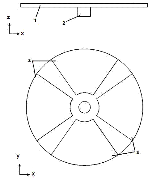
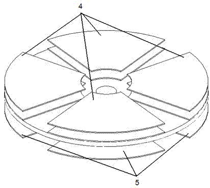
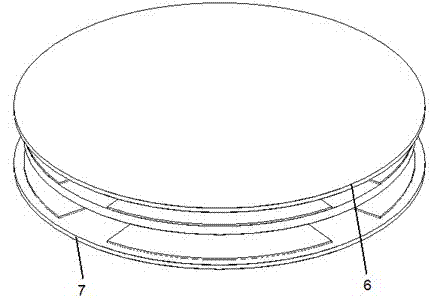
[0027] Such as figure 1 , figure 2 , image 3 As shown, this embodiment includes a gyro vibrator 1 , a support cylinder 2 , a piezoelectric film drive electrode 3 , an upper plate signal detection electrode 4 , a lower plate signal detection electrode 5 , an upper plate 6 , and a lower plate 7 .

[0028] The material of the gyro vibrator 1 is a metal material, and the structure is disc-shaped. One end of the disc-shaped gyro vibrator 1 is the upper surface, and the surface parallel to the other end is the lower surface.

[0029] The support cylinder 2 is m...


PUM


Abstract

The invention belongs to the technical field of micro-electro mechanic systems (MEMS), and relates to a piezoelectricity driven capacitance detecting two-axis gyroscope. According to the invention, a lower surface of a gyroscope oscillator with a shape of a round disc, a wheel spoke or a honeycomb is connected to a supporting cylinder. The other end of the supporting cylinder is fixed on a lower pole plate. The lower pole plate is fixed on a carrier. An upper pole plate signal detecting electrode is positioned on a lower end surface of the upper pole plate. A lower pole plate signal detectingelectrode is positioned on an upper end surface of the lower pole plate. The upper pole plate, the lower pole plate and the gyroscope oscillator are assembled, and differential capacitance is formed for detecting output signals. According to the invention, a special modality of a round disc, a wheel spoke or a honeycomb shape is adopted in the gyroscope oscillator, the detection is driven by piezoelectricity effect, and the detection is carried out by using capacitance. Therefore, angular velocities parallel to the upper and the lower surfaces of the gyroscope oscillator can be sensitively detected. According to the invention, with an MEMS micromachining technology, two-axis detection can be realized, the machining technology is easy to realize, the reliability is high, the energy consumption is low, the impact resistance is high, and the gyroscope can operate well in severe environments.

Description

technical field [0001] The invention relates to a micro-gyroscope in the technical field of micro-electro-mechanical systems, in particular to a piezoelectric-driven capacitance-detection dual-axis gyroscope. Background technique [0002] Gyroscope is an instrument that can accurately measure the angle or angular velocity of a moving object, and is the core component of space object attitude control and inertial guidance. With the development of national defense technology and aviation and aerospace industries, the requirements of inertial navigation systems for gyroscopes are also developing in the direction of small size, multi-axis detection, low power consumption, high reliability, long life, and adaptability to various harsh environments. [0003] After searching the literature of the prior art, it was found that in January 2006, at the IEEE MEMS 2006 conference held in Istanbul, Turkey, K. Maenaka and others from Kobe University in Japan published a paper entitled...

Claims


Application Information

Patent Timeline
Patent Type & Authority Applications(China)
IPC IPC(8): G01C19/56
Inventor 张卫平关冉陈文元吴校生崔峰刘武
Owner SHANGHAI JIAO TONG UNIV
Learn More