
Turbocharger with double vane nozzle system

A turbocharger and double-blade technology, which is applied to gas turbine devices, machines/engines, non-displacement pumps, etc., can solve the problems of reducing the thermal efficiency of the turbine, turbulent air flow, etc., to reduce the cross-sectional area of ​​the channel, reduce the loss of flow resistance, Avoid the effect of air turbulence

Active Publication Date: 2011-12-28
JIANGSU KAIDI DYNAMIC CONTOL SYST CO LTD
View PDF8 Cites 11 Cited by
  • Summary
  • Abstract
  • Description
  • Claims
  • Application Information

AI Technical Summary

Problems solved by technology

Its disadvantages are the same as the second solution. Covering part of the nozzle flow path will cause turbulence in the air flow from the volute to the nozzle inlet, which will also reduce the thermal efficiency of the turbine.

Method used


Image

  • Turbocharger with double vane nozzle system
  • Turbocharger with double vane nozzle system
  • Turbocharger with double vane nozzle system

Examples


Embodiment 1

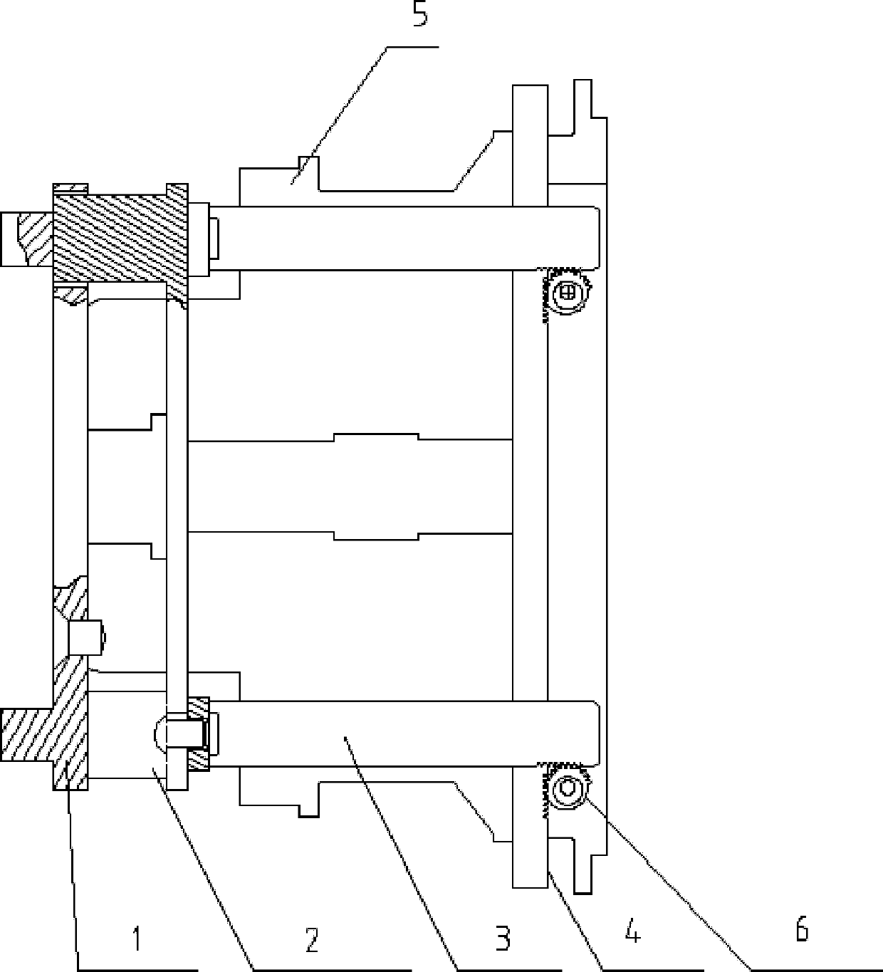
[0028] Take the number of fixed blades 8 as 8, the number of moving blades 7 as 8, and the blade inlet angle, that is, the installation angle, is 21°.

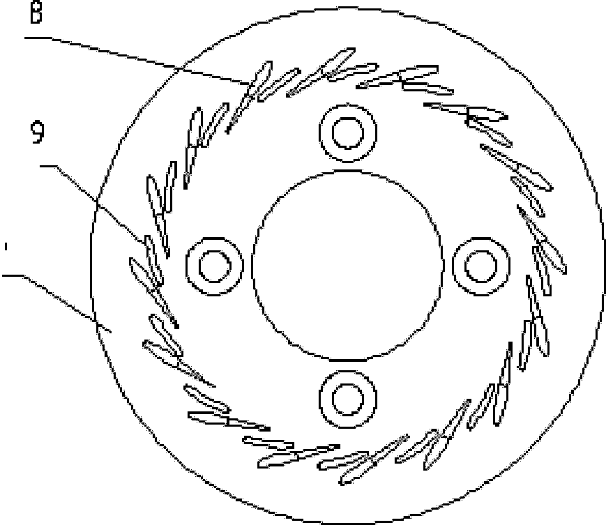
[0029] Such as figure 1 , 4 , 10, there is a set of fixed blades 8 on the front end of the fixed nozzle ring 1, which is shaped like an airfoil, and there are blade-shaped holes 9 between the fixed blades 8, and there is a central hole in the middle of the fixed nozzle ring 1, which is set in the middle shell 5 The outer ring is fixed on the middle shell 5 by screws, and the rear end of the fixed nozzle ring 1 is equipped with a linear movable nozzle plate 2 .

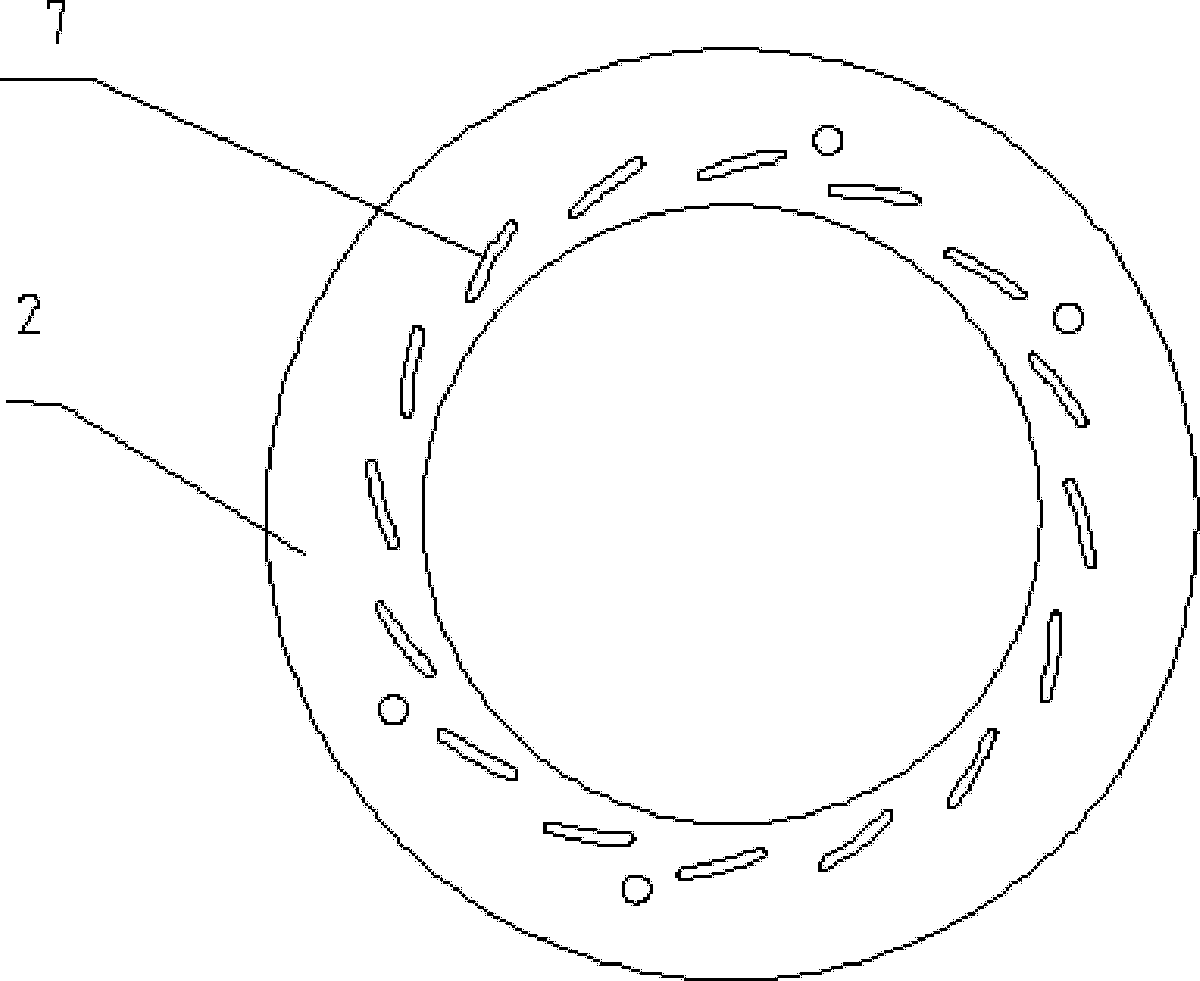
[0030] Such as figure 2 , 10 As shown, there is a group of moving blades 7 on the front end of the linearly moving nozzle plate 2 , the shape of the moving blades 7 is consistent with the shape of the blade hole 9 , and the moving blades 7 are movably inserted in the blade hole 9 .

[0031] Such as figure 1 , 5 , 6, and 10, fix the two rocker levers 3 on the r...

Embodiment 2

[0038] The difference between this embodiment and the first embodiment is that the driving device for pushing the rack to move up and down is a solenoid valve.


PUM


Abstract

The invention provides a turbocharger for double-vane nozzle systems, which comprises a turbine casing, a fixed nozzle ring, a linearly moving nozzle disk, a middle shell, a rack, rocking levers and gears, wing-shaped fixed vanes are arranged on the front end surface of the fixed nozzle ring, vane-shaped holes are arranged between the fixed vanes, the fixed nozzle ring is mounted on the outer circle of the middle shell, and is fixed on the middle shell by bolts, the linearly moving nozzle disk is mounted on the rear end of the fixed nozzle ring, a group of movable vanes are arranged on the front end surface of the linearly moving nozzle disk, and are movably inserted into the vane-shaped holes, the rear end surface of the linearly moving nozzle disk is firmly connected with the two rocking levers, and the rocking levers are inserted into the middle shell, and are engaged with the rack through the gears. Since the new vanes of the turbocharger for double-vane nozzle systems are arranged along a nozzle flow passage, not only can the sectional area of the passage be reduced, but also the original nozzle is divided into two air passages, so that the transverse flow loss of air flow can be reduced. Meanwhile, the air still flows according to the optimal air flow angle of the original design, so the operation of the turbine can be kept in the high-efficiency area.

Description

technical field [0001] The invention relates to a turbocharger of a double-vane nozzle system, which belongs to the field of automobile devices. Background technique [0002] The exhaust gas discharged from the engine works for the turbine in the supercharger and can only work in a narrow and efficient area. Even if the design point of the vehicle supercharger is placed in the range of 50-70%, the supercharger will overspeed when the engine is fully loaded. People add exhaust bypass valve mechanism on supercharger for this reason, to improve its reliability, also wasted the energy of part available combustion gas simultaneously. [0003] The use of adjustable nozzle structure is an effective way to improve the aerodynamic performance of the turbine, and it is also recognized and implemented by various turbocharger manufacturers in the world. There are currently three different solutions: [0004] The patent No. 200710152744.5 "Variable nozzle turbocharger vane assembly and...

Claims


Application Information

Patent Timeline
Patent Type & Authority Applications(China)
IPC IPC(8): F02B37/24F02C6/12F01D9/02F01D17/16
CPCF01D9/02F02B37/24F05D2240/12F05D2220/40F01D17/16F04D17/10Y02T10/144F01D17/165F02C6/12Y02T10/12
Inventor 施永强
Owner JIANGSU KAIDI DYNAMIC CONTOL SYST CO LTD
Learn More