Simple installation structure of unpowered roller shaft

A technology of installation structure and roller shaft, which is applied in the direction of transportation and packaging, conveyor objects, rollers, etc., can solve the problems of complex processing and difficult installation of roller shafts, and achieve improved reliability and installation efficiency, easy processing, and reliable positioning Effect

Inactive Publication Date: 2011-12-28
WUXI JIESI LOGISTICS EQUIP
View PDF5 Cites 0 Cited by
  • Summary
  • Abstract
  • Description
  • Claims
  • Application Information

AI Technical Summary

Problems solved by technology

[0008] Aiming at the disadvantages of complicated processing and difficult installation of the roller shaft in the above-mentioned prior art, the applicant provides a simple installation structure of a non-powered roller shaft with a reasonable structure and easy installation, so that the processing is simple, easy to install and locate

Method used


Image

  • Simple installation structure of unpowered roller shaft
  • Simple installation structure of unpowered roller shaft
  • Simple installation structure of unpowered roller shaft

Examples


Embodiment Construction

[0016] The specific implementation manner of the present invention will be described below in conjunction with the accompanying drawings.

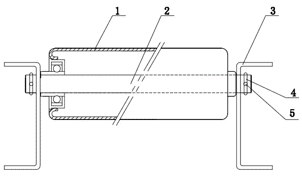
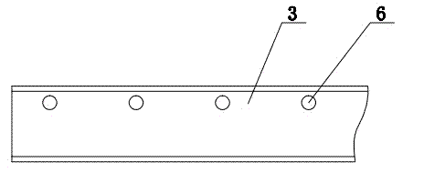
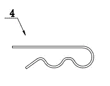
[0017] See figure 1 and figure 2 , the device of the present invention comprises a drum 1, a drum shaft 2 and two side brackets 3, the drum shaft 2 runs through the center of the drum 1, the two ends of the drum shaft 2 are circular body structures, and the two side brackets 3 are respectively opened with There are circular holes 6 matched at both ends of the roller shaft, pin holes 5 are opened at the circular body structure at both ends of the roller shaft 2, and the brackets 3 on both sides are connected with the roller shaft 2 and inserted into the pin holes with R-shaped pins 4 5 positioning (see image 3 ).

[0018] In the actual processing and installation process, the two ends of the drum shaft 2 are processed into a circular body structure, which is inserted into the center of the drum 1, and one end of the circular body struc...


PUM


Abstract

The invention relates to a simple installation structure of a non-powered roller shaft, which includes a roller, a roller shaft, a bearing installed between the roller and the roller shaft, and brackets supporting both ends of the roller shaft. The roller shaft runs through the center of the roller. The two ends of the roller shaft are circular body structures, and the two ends of the roller shaft are respectively provided with pin holes; In the hole, the pin shaft positioning is inserted in the pin shaft holes provided on the circular body at both ends of the drum shaft. The two ends of the roller shaft adopt a circular body structure, which is not only simple in structure, easy to process, and convenient to install. The reliable positioning of the roller shaft can be achieved through the positioning of the circular body structure at both ends and the pin shaft, and no centering is required, which avoids the existing technology. The difficulty of centering causes the installation deviation of the roller shaft, which improves the reliability and installation efficiency of the roller.

Description

technical field [0001] The invention relates to the field of logistics equipment, in particular to a roller conveyor. Background technique [0002] Roller conveyors are generally composed of driving rollers, racks, brackets, driving parts, etc., and are suitable for the transportation of various types of goods such as boxes, bags, and pallets. They are widely used in airports, ports, coal mining industries, and other logistics processing systems. Among them, it can convey a single piece of heavy material and withstand a large impact load. It has the characteristics of large conveying capacity, fast speed, light operation, and can realize multi-variety collinear shunt conveying. [0003] Among them, the roller is mainly used to drive the conveying cylindrical components. According to the driving mode, the rolling structure can be divided into power roller line and non-power roller line. The structure of non-power roller has the advantages of simple structure, high reliabilit...

Claims


Application Information

Patent Timeline
Patent Type & Authority Applications(China)
IPC IPC(8): B65G39/02
Inventor 王建兵
Owner WUXI JIESI LOGISTICS EQUIP
Why Eureka
Try Eureka