
Special core support for sand box for large engine cylinder block

A technology for engine cylinder block and sand box, which is applied to mold boxes, casting equipment, metal processing equipment, etc., can solve the problems of poor deformation prevention effect of sand core, insufficient rigidity and strength of core support, deformation of sand core due to heat, etc. Broad market application prospects, ensuring multi-directional positioning, and the effect of simple core support structure

Inactive Publication Date: 2011-12-28
DONGFENG AUTOMOBILE COMPANY
View PDF2 Cites 8 Cited by
  • Summary
  • Abstract
  • Description
  • Claims
  • Application Information

AI Technical Summary

Problems solved by technology

For smaller sand boxes, there is usually no supporting core in the sand core; and for the sand box used for large engine cylinders (that is, large sand boxes with a volume not less than 1200*950mm*400mm), if there is no supporting core in the sand core , in the molten iron casting process, the sand core must be heated and deformed, resulting in broken core or floating core casting waste (the waste rate is nearly 100%))
In order to solve the above technical problems, it is considered to set an "I" shaped core support on the sand core to fix the sand core and ensure the wall thickness, but this "I" shaped core support can only position the sand core in one direction , the other directions are all positioned by the core head, and the sand core of the sand box for large engine block is a slender structure. After the molten iron is poured, due to the large size of the sand box, the rigidity and strength of the core supporting the sand core are seriously insufficient, and the sand core is seriously insufficient when pouring. The liquid metal pair will also generate buoyancy on the sand core. Under various conditions, the sand core will be severely deformed by heat. The deformation direction is not a single direction, but multi-dimensional and not fixed, resulting in the "I" shaped core support in the actual use process. The effect on the deformation of the sand control core is not good, and the problem of casting waste has not been fundamentally solved (the waste rate is still as high as 15%)

Method used


Image

  • Special core support for sand box for large engine cylinder block
  • Special core support for sand box for large engine cylinder block
  • Special core support for sand box for large engine cylinder block

Examples


Embodiment Construction

[0016] Below in conjunction with accompanying drawing, the present invention will be further explained:

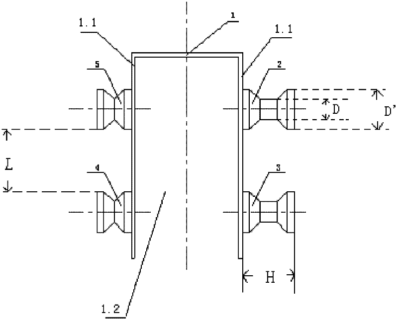
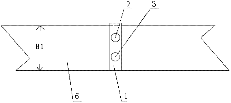
[0017] refer to figure 1 and figure 2 , the present invention includes four dumbbell-shaped pillars (upper right pillar 2, lower right pillar 3, lower left pillar 4 and upper left pillar 5) installed on two side plates 1.1 of saddle-shaped bottom plate 1, each side has 2 pillars respectively, Corresponding to the installation, the height of the pillar H=(0.6-0.9)×the wall thickness of the same side of the sand box; the minimum diameter of the middle section of the pillar is D=(0.2-0.5)×the diameter of the hot spot, and the two ends of the pillar (i.e. dumbbell shape The maximum diameter of the two ends) is 1.5-2 times the minimum diameter. The distance between the pillars on the same side is L=(0.2-0.5)×the sand core height H1. see figure 1 , in this embodiment, because the wall thicknesses of the sand boxes corresponding to the pillars on the two side plates 1.1 are ...


PUM


Abstract

The invention relates to a core support specially used for a sand box for a large-scale engine cylinder body, which solves the problems of unreasonable structure of the core support in the existing large-scale sand box, poor effect on preventing sand core deformation, and high casting waste. The technical solution includes a saddle-shaped base plate, and dumbbell-shaped pillars are correspondingly arranged on both side plates of the base plate. The invention has the advantages of simple structure, convenient installation and good compatibility, can effectively prevent the deformation of the sand core after the molten iron is poured, and greatly reduce the casting rejection rate caused by it.

Description

technical field [0001] The invention relates to a sand box for an engine, in particular to a core support specially used for a sand box for a cylinder body of a large engine. Background technique [0002] There are usually 1-2 long sand cores designed on the side of the sand box for large engine cylinders to reduce the weight of the sand box and improve the mechanical properties of the sand box. For smaller sand boxes, there is usually no supporting core in the sand core; and for the sand box used for large engine cylinders (that is, large sand boxes with a volume not less than 1200*950mm*400mm), if there is no supporting core in the sand core , In the molten iron casting process, the sand core must be heated and deformed, resulting in broken or floating core castings (the rejection rate is nearly 100%)). In order to solve the above technical problems, it is considered to set an "I" shaped core support on the sand core to fix the sand core and ensure the wall thickness, but...

Claims


Application Information

Patent Timeline
IPC IPC(8): B22C21/14
Inventor 吴世云高文平赵学清庞争群黄果果
Owner DONGFENG AUTOMOBILE COMPANY
Learn More