
RS485 splitter and forming method

A technology of RS485 and splitter, applied in the field of RS485 communication system, can solve problems such as poor field application ability, and achieve the effect of enhancing field application ability

Active Publication Date: 2014-07-09
SHENZHEN UNION OPTICAL COMM CO LTD
View PDF4 Cites 0 Cited by
  • Summary
  • Abstract
  • Description
  • Claims
  • Application Information

AI Technical Summary

Problems solved by technology

[0003] It can be seen that due to the limitation of its communication principle, the field application ability of the existing RS485 is poor, and it is necessary to improve it to enhance the field application ability of the bus communication technology based on the principle of differential signal transmission

Method used


Image

  • RS485 splitter and forming method
  • RS485 splitter and forming method
  • RS485 splitter and forming method

Examples


Embodiment Construction

[0029] Below in conjunction with the best embodiment shown in the accompanying drawings, it will be further described in detail.

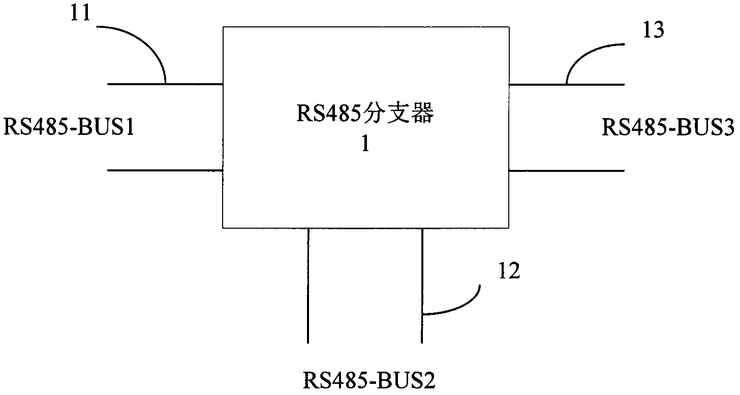
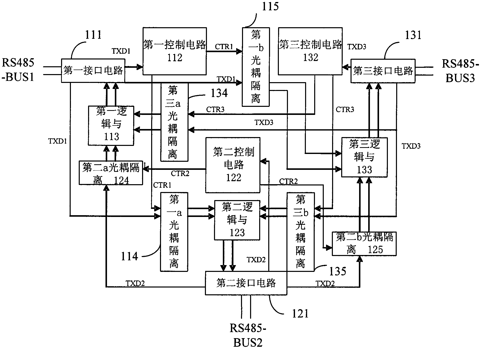
[0030] Such as figure 1 As shown, the RS485 splitter of the present invention includes a branch control circuit 1 and three ports 11, 12 and 13 connected to the branch control circuit 1, each port can be connected to one RS485 communication line RS485-BUS1, RS485-BUS2 or RS485-BUS3. The branch control circuit 1 can automatically transmit the communication signal from the RS485 communication line RS485-BUS1 to the RS485 communication lines RS485-BUS2 and RS485-BUS3 connected to each other port, and transmit the communication signal from the RS485 communication line RS485-BUS3 connected to each other port The communication signals of the RS485 communication line RS485-BUS2 and RS485-BUS3 are transmitted to the RS485 communication line RS485-BUS1, or the communication signals from the RS485 communication line RS485-BUS2 are automatically transmitted ...


PUM


Abstract

The invention discloses an RS485 splitter and a forming method. The RS485 splitter comprises a splitting control circuit and a plurality of ports connected with the splitting control circuit, wherein each port can be connected with an RS485 communication line; and the splitting control circuit can automatically transmit communication signals from each RS485 communication line to the RS485 communication lines connected with each other port and transmit the communication signals from the RS485 communication lines connected with each other port to the RS485 communication line. The RS485 splitter can realize the splitting of three or more paths by a pure hardware circuit design to change an RS485 bus system into point-to-point communication, thereby greatly enhancing the field application capability of a differential-signal-transmission-principle-based bus communication technology.

Description

technical field [0001] The invention relates to an RS485 communication system, in particular to a point-to-point communication device in the RS485 communication system. Background technique [0002] The RS485 bus system is a common serial communication bus system, which is widely used in system construction because of its strong anti-interference ability and long communication distance. However, in practical applications, the entire communication system is often paralyzed due to a single point of failure, and when the system is paralyzed, it is difficult to locate the fault point, and a certain strategy must be adopted to check point by point, making the maintenance cost of the system very high. In addition, the construction wiring is also limited, and the number of communication nodes is limited, which makes the construction of the system more complicated. [0003] It can be seen that due to the limitation of its communication principle, the field application ability of t...

Claims


Application Information

Patent Timeline
Patent Type & Authority Patents(China)
IPC IPC(8): H04L12/40
Inventor 杨泽清
Owner SHENZHEN UNION OPTICAL COMM CO LTD
Learn More